




Contents: Main dosing system ↓ Idle system ↓ Transitional systems ↓ Power mode economizer ↓ Econostat ↓ Accelerator pump ↓ Starting device ↓ Forced idle economizer ↓ Blocking the second mixing chamber…↓
The VAZ-21219 car is equipped with a 21073-1107010 carburetor (Fig. 9-5), an emulsion type, two-chamber, with sequential opening of the throttle valves. The carburetor has a balanced float chamber, a system for sucking crankcase gases behind the throttle valve, heating of the throttle valve zone of the first chamber, and a lock for the second chamber.
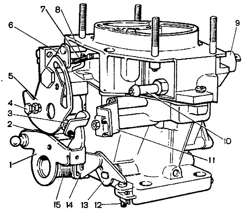
Fig. 9-5. External appearance of carburetor 21073-1107010: 1 - throttle valve drive lever; 2 - pin of the second chamber locking lever; 3 - adjusting screw for opening the throttle valve of the first chamber; 4 - air damper drive rod mounting screw; 5 - air damper control lever; 6 - air damper lever; 7 - air damper return spring; 8 - diaphragm rod of the starting device; 9 - electromagnetic shut-off valve; 10 - fuel supply pipe; 11 - bracket for fastening the air damper drive rod casing; 12 - adjusting screw of the second chamber, 13 - throttle lever of the second chamber; 14 - second chamber throttle actuator lever; 15 - return spring of the first chamber throttle valve.
The carburetor has two main metering systems of the first and second chambers, an idle system of the first chamber with a transition system, a transition system of the second chamber, an economizer of power modes, an economizer, a diaphragm accelerator pump, a starting device. At forced idle, the economizer of forced idle is switched on.
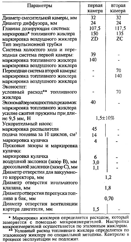
The carburetor calibration data are given in Table 9-2.
Table 9-2. Calibration data for carburetor 21073-1107010
Main dosing system
Fuel is fed into the float chamber through mesh filter 4 (Fig. 9-6) and needle valve 6. From the float chamber, fuel enters the emulsion wells through main fuel jets 9 and mixes with air coming out of the holes of emulsion tubes 1, which are made integral with the main air jets. Through sprayers 2, the fuel-air emulsion enters the small and large diffusers of the carburetor.
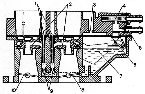
Fig. 9-6. Diagram of the main metering systems of the carburetor 21073-1107010: 1 - main air jets with emulsion tubes; 2 - first and second chamber sprayers; 3 - balancing hole; 4 - fuel filter; 5 - a branch pipe with a calibrated hole for draining part of the fuel into the fuel tank; 6 - needle valve; 7 - float; 8 - second chamber throttle valve; 9 - main fuel jets; 10 - first chamber throttle valve.
Throttle valves 8 and 10 are connected to each other in such a way that the second chamber begins to open when the first is already open by 2/3 of its size.
Idle system
The idle system takes fuel from the emulsion well after the main fuel jet 7 (Fig. 9-7). Fuel is supplied to the fuel jet 2 with the electromagnetic shut-off valve 1, at the outlet of the jet it is mixed with air coming from the flow channel and from the expanding part of the diffuser (to ensure normal operation of the carburetor when switching to idle mode). The emulsion comes out under the throttle valve through an opening adjusted by screw 9 of the mixture quality (composition).
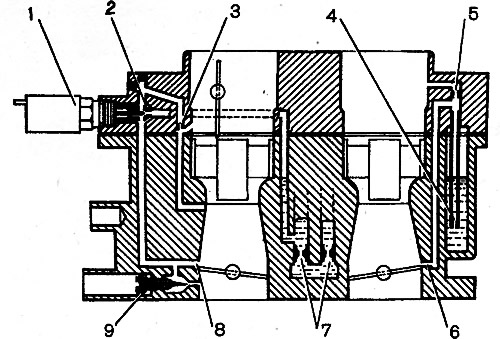
Fig. 9-7. Idle system and transition systems diagram of the 21073-1107010 carburetor: 1 - electromagnetic shut-off valve; 2 - idle fuel jet; 3 - idle air jet; 4 - fuel jet of the transition system of the second chamber with a tube; 5 - air jet of the transition system of the second chamber, 6 - outlet of the transition system of the second chamber; 7 - main fuel systems; 8 - first chamber transition system slit; 9 - adjusting screw for idle mixture quality (composition).
Transitional systems
When the carburetor throttle valves are opened before the main metering systems are switched on, the fuel-air mixture enters:
- into the first mixing chamber through the idle jet 2 and the vertical slot 8 of the transition system, located at the level of the edge of the throttle valve in the closed position;
- into the second mixing chamber through the outlet 6, located slightly above the edge of the throttle valve in the closed position. Fuel comes from the jet 4 through the tube, mixes with air from the jet 5, entering through the flow channel.
Power mode economizer
The power mode economizer operates at a certain vacuum behind the throttle valve 5 (Fig. 9-8). Fuel is taken from the float chamber through the ball valve 8. Valve 8 is closed while the diaphragm is held by the vacuum in the intake pipe. When the throttle valve is opened significantly, the vacuum drops somewhat and the diaphragm spring 7 opens the valve. The fuel passing through the economizer jet 9 is added to the fuel passing through the main fuel jet 4, enriching the combustible mixture.
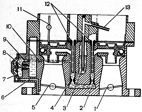
Fig. 9-8. Scheme of economizer and economizer of power modes: 1 - throttle valve of the second chamber; 2 - main fuel jet of the second chamber; 3 - fuel jet economizer with tube; 4 - main fuel jet of the first chamber; 5 - first chamber throttle valve; 6 - vacuum supply channel; 7 - economizer diaphragm; 8 - ball valve; 9 - fuel jet economizer; 10 - fuel channel; 11 - air damper; 12 - main air jets; 13 - economizer injection tube
Econostat
The economizer operates at full engine load at speeds close to maximum, with the throttle valves fully open. Fuel from the float chamber through jet 3 (see fig. 9-8) enters the fuel pipe and is sucked out through the injection pipe 13 into the second mixing chamber, enriching the combustible mixture.
Accelerator pump
The accelerator pump is diaphragm-type, with a mechanical drive from cam 6 (Fig. 9-9) on the axis of the throttle valve of the first chamber. When the throttle valve is closed, the spring moves diaphragm 3 back, which leads to filling the pump cavity with fuel through ball valve 8. When the throttle valve is opened, the cam acts on lever 5, and diaphragm 3 pumps fuel through ball valve 2 and sprayer 1 into the mixing chamber of the carburetor, enriching the combustible mixture.
The pump performance is not adjustable and depends only on the cam profile.
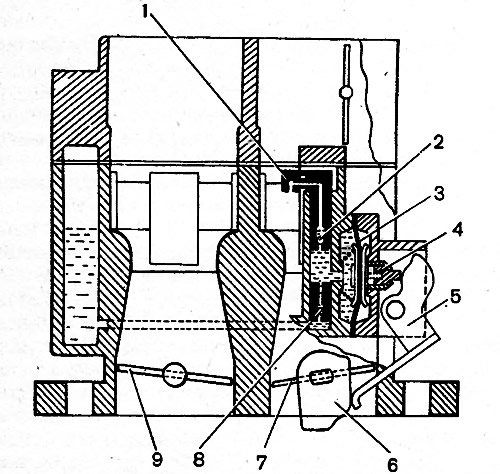
Fig. 9-9. Schematic diagram of the accelerator pump of the carburetor 21073-1107010: 1 - sprayer; 2 - fuel supply ball valve; 3 - pump diaphragm; 4 - pusher; 5 - drive lever; 6 - pump drive cam; 7 - first chamber throttle valve; 8 - check ball valve; 9 - second chamber throttle valve.
Starting device
Lever 4 (Fig. 9-10) for controlling the air damper has three profiles. Its outer edge 4.3 acts on lever 11 for controlling the throttle valves through adjusting screw 10 and ensures starting a cold engine and the subsequent necessary increase in the engine crankshaft speed. Inner profiles 41 and 4.2 act on lever 6 of the air damper and allow it to open at intermediate positions of lever 4 by a certain amount. When turning lever 4 for controlling the air damper counterclockwise, the expanding groove releases the pin of lever 6 of the air damper, and due to return spring 7 the damper will be held completely closed. At the same time, lever 4 with edge 4.3 slightly opens the throttle valve of the first chamber.
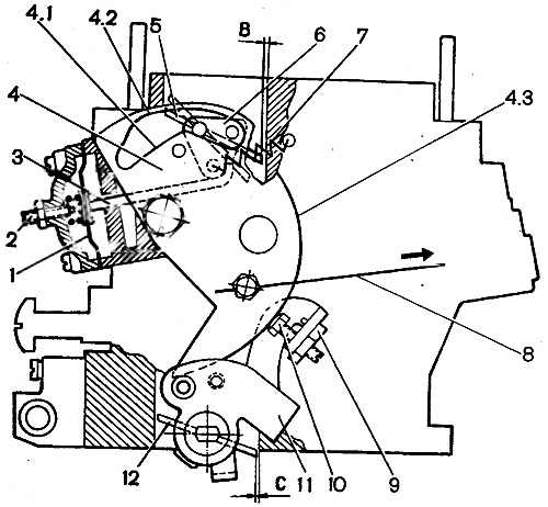
Fig. 9-10. Diagram of the starting device of the carburetor 21073-1107010: 1 - diaphragm; 2 - adjusting screw; 3 - diaphragm rod; 4 - air damper control lever; 4.1 - lower profile of the groove of the lever 4 for limiting the maximum opening of the air damper; 4.2 - upper groove profile providing mechanical opening of the air damper; 4.3 - edge of lever 4 to provide starting clearance of the first chamber throttle valve; 5 - air damper; 6 - air damper lever; 7 - air damper return spring; 8 - air damper drive rod; 9 - adjusting screw stopper; 10 - first chamber throttle valve opening adjusting screw; 11 - throttle actuator lever; 12 - first chamber throttle valve; B - starting clearance at the air damper, C - starting clearance at the throttle valve
The axis of the air damper 5 is offset, so after starting the engine the air damper can open slightly due to the air flow, stretching the spring 7, which ensures the leaner mixture.
The vacuum from the throttle space acts on the diaphragm 1 and opens the air damper with the rod 3. The adjusting screw 2 allows you to regulate the amount of opening of the air damper.
The maximum amount of opening of the air damper when starting and warming up the engine depends on the intermediate positions of the air damper control lever 4 or on the width of the groove of this lever.
Forced idle economizer
The forced idle economizer disables the idle system at forced idle (when braking the car with the engine, when driving downhill, when changing gears), eliminating the emission of carbon monoxide into the atmosphere.
In the forced idle mode at a crankshaft speed of more than 2100 min⁻¹ and with limit switch 1 closed to ground (see fig. 9-26) carburetor (pedal released) shut-off electromagnetic valve 4 switches off, fuel supply is interrupted.
The text is copied from the online resource: VAZBOOK.RU
When the crankshaft speed at forced idle speed decreases to 1900 min⁻¹ the control unit switches on the electromagnetic shut-off valve (although the limit switch is connected to ground), fuel supply begins through the idle jet, and the engine gradually reaches idle speed.
Blocking the second mixing chamber of the carburetor
The throttle valve of the second chamber can be opened only when the air damper is open by the second chamber locking lever installed on lever 1 (see fig. 9-5). When the throttle valves are opened, the locking lever acts through the lever 14 of the second chamber throttle valve drive on the lever 13 of the second chamber throttle valve.
When the air damper is closed, the outer edge of lever 5 acts on pin 2 of the locking lever and disconnects it from lever 14. In this position, the throttle valve of the second chamber is blocked and cannot be opened.