

Disassembly
Rinse the gearbox and install it on the stand. Drain the oil and remove the bottom cover with gasket.
Remove the clutch release fork, and from the guide sleeve of the front cover of the gearbox - the clutch assembly with the bearing and the connecting spring.
Remove the clutch housing with gasket and transmission front cover (complete with seal and spring washer) (pic. 3-15).
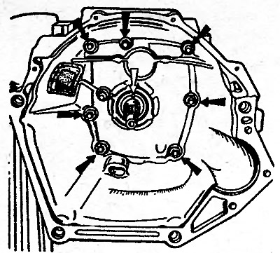
Pic. 3-15. Interior view of the clutch housing. Black arrows indicate the nuts securing the clutch housing to the gearbox; the white arrow indicates the hole in the front cover to drain the oil from the gearbox housing so that the clutch discs do not get oiled
Unscrew the reversing light switch, being careful not to deform its housing.
Turn out a bolt of fastening of a plug of switching of III and IV transfers. Install clamp 41.7816.4068 on the input shaft or simultaneously engage two gears. This will prevent rotation of the input, output and countershafts and allow subsequent disassembly operations.
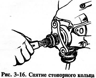
Remove the retaining ring from the end of the output shaft of the gearbox (pic. 3-16).
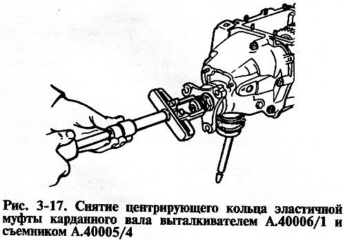
After unbending the lock washer, loosen the nut a few turns to move the centering ring of the elastic coupling, and tighten the nut again. Using A.40006/1 ejector with A.40005/4 puller, remove from the end of the secondary shaft the centering ring of the flexible coupling of the cardan shaft (pic. 3-17).
Remove the seal of the centering ring of the elastic coupling with the spring from the end of the secondary shaft, unscrew the nut and remove the flange of the elastic coupling with a puller A.40005/3/9B/9C (pic. 3-18).
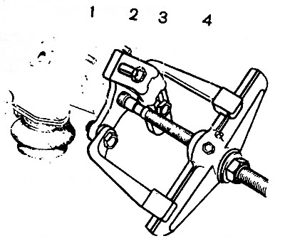
Pic. 3-18. Removing the flexible coupling flange with a puller А.40005/3/9В/9С: 1 - flange of an elastic coupling; 2 - bolts for fastening the device to the flange, 3 - stripper strip A.40005/3; 4 - puller А.40005/3
Remove the gearbox rear cover by unscrewing its fastening nuts and screw 4 (pic. 3-19) limiting the transverse travel of the lever, as well as moving the growl to the left: shifting gears to free it from the gear shifting rods.
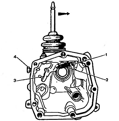
Pic. 3-19. Inside view of the rear cover of the gearbox: 1 - screw with an eye for fastening the withdrawal spring of the shift lever; 2 - lever spring, 3 - gear lever; 4 - screw limiting the transverse travel of the lever. The arrow indicates the direction in which you need to move the lever to disengage it from the rod heads and remove the rear cover of the gearbox
Remove the rear bearing from the output shaft and then the bearing spacer.
Remove the fork with spacer from the reverse gear rod, and the reverse idler gear from the axle.
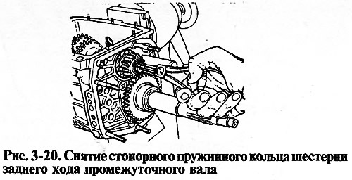
Remove the reverse gear retaining ring from the countershaft (pic. 3-20); Remove gear and spring washer.
Remove the circlip of the reverse driven gear from the secondary shaft, pressing the spring washer with a mandrel 41.7816.4069 to relieve the load from the circlip. Remove the reverse driven gear and spring washer.
With the help of curly mandrels (screwdriver type) and rod drifts, remove the front and rear bearings of the intermediate shaft from the gearbox housing. On the inner rings of the double-row front bearing, put marks on which these rings should be installed in their original places in the outer ring of the bearing.
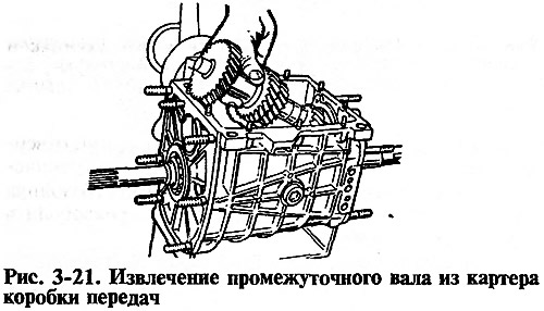
Remove the intermediate shaft from the gearbox housing. tilting it as shown in Figure 3-21.
Remove cover 20 (pic. 3-22) rod clamps together with the gasket, remove the rod 18 of the reverse gear fork, the rod 17 of the shift fork of III and IV gears from the gearbox housing. Turn away a bolt of fastening of a plug of I and II transfers, take out a rod and plugs. When removing the rods, simultaneously remove the three blocking crackers 19. Remove the lock plate (pic. 3-23) intermediate bearing of the secondary shaft and the axis of the intermediate reverse gear.
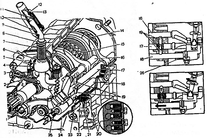
Pic. 3-22. Gear shift drive: 1 - fork of inclusion of a backing; 2 - retraction spring of the gear lever; 3 - guide cup of the lever; 4 - ball bearing of the lever, 5 - gear lever, 6 - spherical washer; 7 - lever spring; 8 - retaining ring; 9 - locking sleeve; 10 - elastic bushings, 11 - remote bushing; 12 - persistent on; ear; 13 - gear lever rod; 14 - fork of inclusion of III and IV gears; 15 - fork of inclusion of I and II transfers; 16 - a rod of a fork of inclusion of I and II transfers; 17-rod of the fork of inclusion of III and IV gears; 18 - reverse fork rod; 19 - block crackers; 20 - cover of clamps; 21 - bushing; 22 - retainer spring; 23 - retainer ball; 24 - rear cover of the gearbox; 25 - reversing light switch; 26 - remote bushing of the reverse fork rod
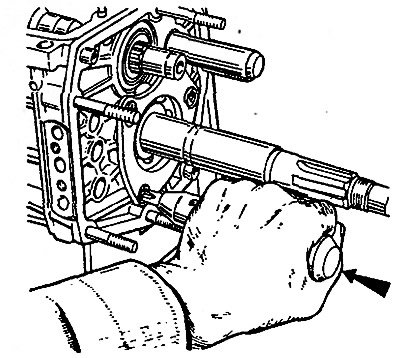
Pic. 3-23. Unscrewing the screws securing the locking plate of the intermediate bearing of the secondary shaft with a drill screwdriver. The arrow shows the direction of the impact stroke of the screwdriver holder (when hit with a hammer).
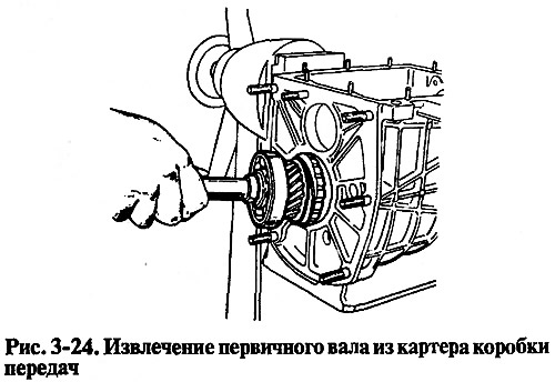
With mandrels (screwdriver type) remove the input shaft together with the bearing and synchronizer ring (pic. 3-24) and remove the needle bearing from the front end of the output shaft.
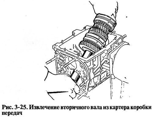
Knock out the secondary shaft from the intermediate bearing, remove the intermediate bearing and, tilting as shown in fig. 3-25, remove the output shaft assembly with gears, clutches and synchronizer rings from the crankcase. Remove the 3rd and 4th gear synchronizer coupling from the shaft.
Disassemble the input shaft (pic. 3-26):
- remove the retaining ring 7, blocking ring 6 and synchronizer spring 5;
- install the shaft on the press and, compressing the spring washer 2 with the mandrel 41.7816.4069, remove the retaining ring 1, and then the spring washer and bearing 3.
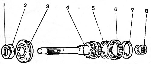
Pic. 3-26. Main shaft details: 1 - retaining ring; 2 - spring washer; 3 - bearing; 4 - input shaft; 5 - synchronizer spring, 6 - synchronizer blocking ring; 7 - retaining ring; 8 - bearing
Disassemble the output shaft (pic. 3-27):
- remove from the rear side of the shaft gear 121 - gears with sleeve 13, hub 3 with a sliding clutch for switching I and II gears, gear 11 of the second gear together with blocking ring 5 of the synchronizer;
- install the secondary shaft with mandrel 41.7816.4069 on the press (see fig. 3-28), place support half rings 3 under the gear of the III gear, and, pressing the mandrel on the spring washer, remove the retaining ring 2, then the spring washer 4, the hub of the sliding clutch of the III and IV gears and the gear of the III gear.
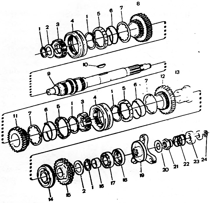
Pic. 3-27. Output shaft details: 1 - retaining ring; 2 - spring washer; 3 - synchronizer hub; 4 - synchronizer clutch; 5 - synchronizer blocking ring; 6 - synchronizer spring; 7 - washer; 8 - gear of the III gear; 9 - secondary shaft; 10 - key, 11 - gear of the 2nd gear, 12 - gear of the 1st gear; 13 - bushing gear 1st gear; 14 - bearing; 15 - reverse gear; 16 - spacer sleeve; 17 - rear bearing; 18 - stuffing box; 19 flange of the elastic coupling, 20 - lock washer; 21 - nut; 22 - spring seal, 23 - seal; 24 - centering ring
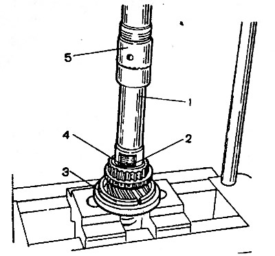
Pic. 3-28. Installation on the secondary shaft of the retaining ring: 1 - mandrel 41.781b.40o9; 2 - retaining ring; 3 - support half ring; 4 - spring washer; 5 - press rod
Disassemble the shift lever and rear cover:
- remove cuff 19 (pic. 3-29), a cover 20 of the lever, then a locking ring 14, a washer 13, a spring 12 and a spherical washer 11;
- unscrew the flange fastening nuts 16, disconnect the release spring 3 of the lever from the eye of the bolt 1 and remove the lever together with the flange, support 10 and cup 5.
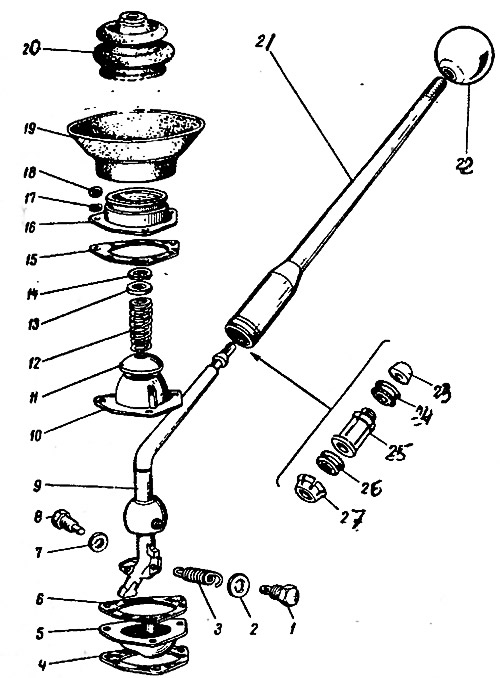
Pic. 3-29. Shift Lever Details: 1 - bolt of the return spring; 2 - washer; 3 - withdrawal spring; 4 - gasket; 5 - guide cup; 6 - gasket; 7 - washer, 8 - restrictive bolt; 9 - gear lever; 10 - ball bearing; 11 - spherical washer; 12 - spring; 13 - support washer; 14 - retaining ring; 15 - gasket; 16 - flange; 17 - spring washer; 18 - nut; 19 - cuff; 20 - inner cover; 21 - lever rod; 22 - handle, 23 - thrust pad; 24 - elastic sleeve; 25 - remote bushing; 26 - elastic sleeve; 27 - locking sleeve
Assembly
The assembly of the gearbox is carried out in the reverse order of disassembly. In doing so, keep in mind that:
- spring 22 (pic. 3-22) the reversing fork rod retainer ball differs from others in elasticity, it is painted green or has a cadmium coating, and since 1985 it has been black oxidized;
- when installing the clutch housing with the front cover of the gearbox, the hole in the front cover must be located as shown in fig. 3-15;
- before installation, cover the working surface of the seals with LITOL-24 grease;
- when installing the reverse gear retaining ring, use drift 41.7816.4069, as shown in fig. 3-30, and when installing bearings and shaft seals, use mandrels 41.7853.4028, 41.7853.4032, 41.7853.4039.
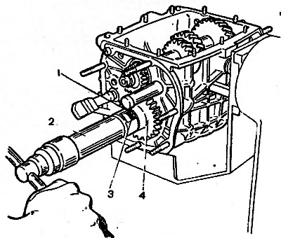
Pic. 3-30. Installation on the secondary shaft of the retaining ring of the reverse gear: 1 - locking ring; 2 - mandrel 41.7816.4069; 3 - spring washer, 4 - secondary shaft reverse gear