
Unscrew the screws securing the armrest, after removing the decorative plastic plug 1 (pic. 8-13) top screw, and remove the armrest.
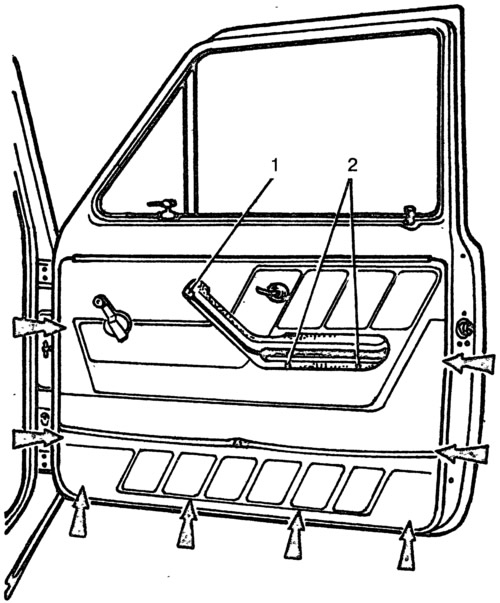
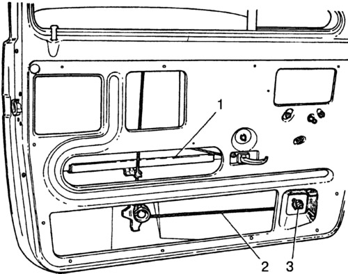
Pic. 8-13. Interior view of the front door:
1 - plug of the upper armrest mounting screw; 2 - lower armrest mounting screws. The arrows show the location of the door upholstery holders.
Press socket 20 (pic. 8-14), take out facing 1 and remove the window regulator handle 2. Prying off the lining of the inner handle of the lock drive with a screwdriver, remove the lining.
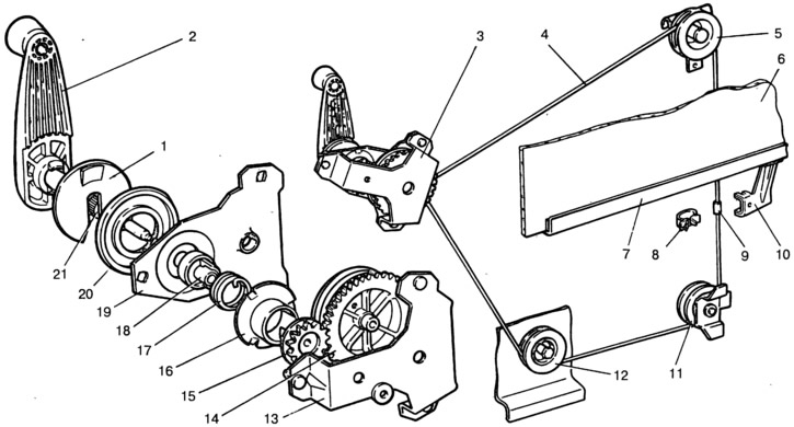
Pic. 8-14. Sliding window drive:
1 - lining of the window handle; 2 - power window handle; 3 - power window mechanism; 4 - cable; 5 - top roller; 6 - sliding glass; 7 - clip of the sliding glass; 8 - cable holder; 9 - cable clutch; 10 - glass holder bracket; 11 - lower roller; 12 - tension roller; 13 - power window mechanism housing; 14 - drum with driven gear; 15 - drive gear; 16 - support of the drive roller; 17 - brake spring; 18 - spring brake leash; 19 - housing cover; 20 - socket; 21 - drive roller.
Overcoming the resistance of spring plastic holders (in fig. 8-13 marked with arrows), remove the door trim.
With the sliding window in the up position, remove the mounting screws and remove the front and rear guide grooves of the sliding window.
Lower the glass down and loosen the window tensioner roller nut. Disconnect the cable from the lowering glass cage and remove it from the rollers. While holding the cable taut, unscrew the fastening nuts and remove the power window mechanism. Clamp the cable strands at the exit from the drum with a wire clamp. Take out glass through the lower aperture of a door.
Remove the sliding window seals and the pivot glass assembly by unscrewing the fixing screws.
Unscrew button 6 (pic. 8-15) lock, unscrew the screws securing the bracket 4 of the inner handle 1 of the lock drive, unscrew the screws 3 (pic. 8-16) fixing the lock body and remove the lock with rods, having previously disconnected the rod 20 (see fig. 8-15) from the lock switch.
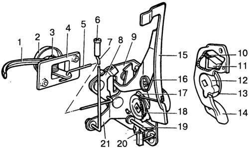
Pic. 8-15. Front left door lock:
1 - inner door handle; 2 - lining of the inner handle; 3 - axis; 4 - bracket for the inner handle; 5 - thrust of the inner handle; 6 - lock lock button; 7 - thrust of the lock button; 8 - lever of the internal drive of the lock; 9 - lock case; 10 - cracker spring; 11 - cracker of the lock retainer; 12 - rotor; 13 - support of the central roller; 14 - latch body; 15 - external drive lever; 16 - spring of the external drive lever; 17 - ratchet; 18 - ratchet spring; 19 - roller off the lock; 20 - thrust off the lock; 21 - lock lever.
Pic. 8-16. Front door lock fixing:
1 - lock lock button; 2 - thrust of the lock button; 3 - lock fixing screws.
Remove the outer door handle by unscrewing the two fastening nuts.
Turn out two bolts of fastening and remove the limiter of opening of a door.
Assemble the front doors in the reverse order of disassembly.
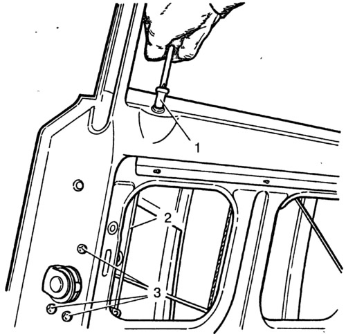
When installing the power window, make sure that the coils of the cable on the drum do not overlap. Adjust cable tension 2 (pic. 8-17) and smooth operation of the power window by moving the tension roller, loosening the nut 3.
Pic. 8-17. Power window cable tension adjustment:
1 - holder of the sliding glass; 2 - cable; 3 - a nut of a bolt of a tension roller.
Before installing the door upholstery, check the condition of the plastic upholstery holders.