

Open large image in new tab »
On cars «Oka» a single-wire circuit for switching on electrical equipment is used, that is, only one wire is suitable for all consumers of electricity. Second «by wire», connecting consumers to sources of electricity is the car body, or «weight». This scheme allows you to significantly reduce the number of wires and simplify their installation. The negative terminals of the power sources are connected to the ground. With this connection, corrosion of metal body parts due to electrochemical corrosion is reduced.
The sources of electricity in a car are a generator and a battery connected in parallel. The rated operating voltage of sources and consumers of electricity is 12 V. However, the voltage in the electrical equipment system, depending on specific conditions, can vary from 11 to 14.5 V, and within these limits, consumers retain their performance.
All electrical equipment of cars can be divided into the following main systems:
- 1) a power supply system that includes a battery and a generator with a voltage regulator;
- 2) engine start system, which includes the starter, starter relay and the corresponding contacts of the ignition switch;
- 3) ignition system, consisting of an ignition coil, a spark moment sensor, a switch, spark plugs, high voltage wires, an ignition relay and corresponding ignition switch contacts;
- 4) a lighting and light signaling system that combines headlights, lanterns and related switches and relays;
- 5) control devices with sensors;
- 6) additional electrical equipment, which includes a cleaner and washer for the wind and rear windows, a rear window heating system, a heater electric motor, a cigarette lighter and a sound signal.
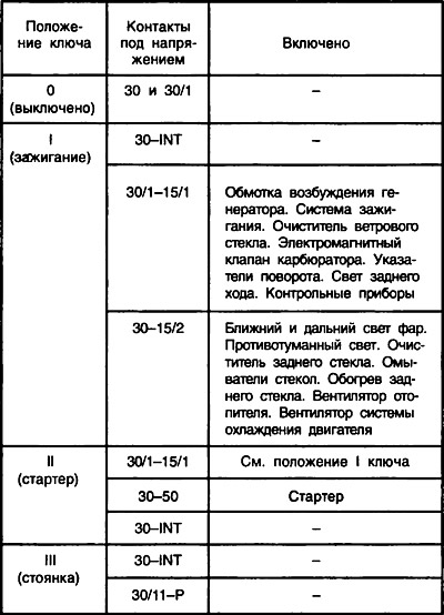
The operation and activation of all systems are controlled by appropriate switches and relays. The supply voltage to most consumers is supplied through the ignition switch 31. The switched circuits for various key positions are shown in the table (see also ch. 32).
The power circuits of those electrical equipment components, the operation of which may be required under any circumstances, are always connected to the battery and generator (regardless of the position of the key in the ignition switch). Such nodes include a horn 4, a cigarette lighter 45, brake light filaments in the rear lights 68, license plate lights 70, a ceiling light 58, and a socket 11 for a portable lamp. Also directly connected to the power sources of the alarm circuit, side light and high beam signaling circuit.
During the operation of vehicles, there may be cases of short circuits due to damage to the insulation of wires or electrical equipment. They cause a sharp increase in the current strength in a short-circuited circuit and, if protective measures are not taken, can lead to a rapid discharge of the battery, overheating of the wires, melting of their insulation and ignition of the upholstery of the car.
There are 11 fuses on the vehicle for short circuit protection. Ten of them are located in the plastic block 22, and one fuse 32 protecting the purpose of the rear fog light is located in a separate housing in the wiring harness near the rear fog light switch 41. This fuse is rated for a maximum current of 8 A.
The fuse box is located under the instrument panel on the left side of the steering column. Fuses are a thin plate of low-melting metal, fixed on a plastic base. Seven fuses (black color) are rated for a maximum current of 8 A, and three (Green colour) - 16 A. 16 A fuses are in the power circuits of electrical equipment components that consume high current (such as rear window defogger, cigarette lighter, engine cooling fan motor, etc.).
Below are the circuits protected by the fuses located in the fuse box.
If a fuse blows, it is recommended to check the circuits it protects, repair the fault that caused the blown, and then install a new fuse. It is not allowed to use any homemade fuses and fuses that are not provided for by the vehicle design.
The largest number of fuses is installed in the lighting system, since it has the most extensive and extended network of wires and is therefore most susceptible to damage and short circuits with ground. The electric motors of the windshield and rear window cleaners are additionally protected against overloads by thermal bimetallic fuses located in the electric motors themselves. The cigarette lighter is additionally protected against prolonged switching on by a low-melting alloy washer located at the rear of the cigarette lighter.
Some power supply circuits of electrical equipment do not have fuses at all. As a rule, these are the most critical systems, the failure-free operation of which is required in emergency situations. For example, the engine ignition system is not protected by fuses so as not to introduce elements into it that reduce the reliability of the system in operation. If the ignition system fails, the engine will stop working. There are also no fuses in the starting circuit so as not to reduce the reliability of starting the engine. In addition, the battery charging circuit, as well as the relay for switching on the high and low beam headlights, are not protected by fuses.
To connect sources and consumers of electricity into a common circuit on cars, flexible low-voltage wires of the PVA type are used (high voltage wires are described further on sheet 32). They have a strong elastic insulation made of polyvinyl chloride plastic compound. Such insulation is resistant to oil, gasoline and is operable in the temperature range from -40 to 105°C. The conductive core of the wires is made of a large number of soft copper wires to ensure flexibility (from 19 for a wire with a cross section of 1 mm2 up to 84 for 16 mm wire2).
In order to distinguish the wires in the bundles and easily trace their connections, the wire insulation is made in different colors. It can be dyed in a wide range of colors: white, blue, yellow, red, etc. In addition, spiral or longitudinal stripes of white, red, blue or black can be applied to the surface of the insulation. Thus, no two wires of the same color are found in the wiring harnesses. Black wires are used for ground connection, and black wires for connection with «a plus» power sources are mostly pink or orange. The current flowing through the wires heats them up. In addition, there is a voltage drop in the wires. To ensure that the heating and voltage drop do not exceed the permissible limits, it is necessary to select the appropriate cross-section of the conductive conductors of the wires. The greater the electric current flows, the larger the cross section of the wire core should be. Therefore, on cars, wires with different cross-sections of the core are used: 16; 4; 2.5; 1.5; 1.0; 0.75 and 0.5 mm2.
The largest current flows when starting the engine through the wires connecting the battery to the starter and ground, as well as the engine to ground. These wires are 16mm2. A fairly significant current also flows through the wire connecting the generator to the starter when the battery is charging, as well as when the engine is not running, when all consumers are powered from the battery. Therefore, this wire is selected with a cross section of 4 mm2. The same wire connects the plug «87» relay 25 starter enable with plug «50» traction starter relay 6.
Wires with a cross section of 2.5 mm2 used to supply voltage from the fuse box to headlight bulbs, to connect plugs «30» and «87» relays 24, 25, 27 and 28 with consumers or a fuse box and for connecting the electric motor 3 of the engine cooling fan with relay 24 and ground. The same wires go to the contacts «30», «30/1», «15» and «15/1» ignition switch 31 and to the contacts «D», «I» and «I» switch 44 outdoor lighting.
Wires with a cross section of 1.5 mm2 are used to connect the rear window heating element 64 with the relay 26 for turning on the heating and for connecting the plug «87» this relay with the fuse box.
All other car wires have a cross-section of a conductive core from 0.5 to 1 mm2, since a relatively small current flows through them.
The wires are connected to the electrical equipment nodes and interconnected using convenient quick connectors. An exception is the connection of wires to the battery, to the clamp «30» generator and to the bolt of the starter traction relay. At these critical connections, the wire lugs are clamped with nuts to ensure maximum reliability of the connections.
To protect the electrical connections from water and dirt, the rear of the front direction indicators are covered with covers. Protective rubber caps cover the lugs of high voltage wires, coolant temperature and oil pressure sensors, terminal «plus» battery, reverse light switch. Also capped are the sockets for side turn signal lamps, rear fog lamps and license plate lamps.
To facilitate installation, all wires are bundled. Wires in bundles are wrapped with adhesive tape or enclosed in plastic tubes. The harnesses are connected to each other by means of plug connectors, the pads of which are made of polyamide plastic. The holes in the body through which the wires pass are closed with rubber seals, which protect the wires from damage on the edges of the holes and prevent water and dirt from penetrating through the holes.
There are four wiring harnesses in total, front (basic) harness, rear, front turn signal harness (2 pcs.) and battery harness.
Main wiring harness - front. It has three branches. Two of them are in the engine compartment, and the third is in the cabin under the instrument panel. From the passenger compartment to the engine compartment, the wiring harness passes through the rubber seal and branches out after exiting it. The right branch of the harness is laid on the bulkhead shield, and the left branch is on the left mudguard and the front panel of the bulkhead. The wiring harness is attached to the body panels with steel brackets welded to the body and plastic clamps.
The harness must be fastened in such a way that it is not too tight, but also does not dangle, as this can lead to chafing of the wires during shaking and shorting them to ground.
In the passenger compartment, the front harness runs under the instrument panel and has small branches to the fuse box, to the switches, to the instrument cluster, to the ignition switch and to other electrical components. A fuse box is installed on the left side under the instrument panel, and all auxiliary relays are fixed on the bracket behind it (except ignition relay).
The front harness is connected to the rear wiring harness using three plug connectors: two-pin, six-pin and eight-pin. The rear harness runs back under the floor mats on the left side of the body floor and has branches to the right side turn signal and dome light switch in the right door pillar, to the parking brake warning light switch, up to the dome light, and down in front of the rear seat to the right rear light. From the rear right lamp, the harness goes up and, near the right hinge of the rear door, goes to the door and goes to the rear window wiper gearmotor and the rear window heating element. The rear harness is attached to the body floor with adhesive tape.
Some units of electrical equipment are installed only on a part of manufactured cars.
These include the cigarette lighter, rear fog light with switch, and electrically heated rear window with appropriate relay and switch.
| fuse no | Protected circuits |
| 1 (16 A) | Heater fan motor. Relay (winding) and a sensor for turning on the electric motor of the fan of the engine cooling system. Relay (winding) turning on the heated rear window. Electric motors for wiper, rear window washer and windshield washer. |
| 2 (8 A) | Carburetor solenoid valve. Relay and windshield wiper motor. Direction indicators and relay-interrupter of direction indicators and alarms (in turn guidance mode). Control lamp of indexes of turn. Rear lights (reversing light bulbs). Generator excitation winding (when starting the engine). Carburetor choke control lamp. Relay-breaker and control lamp of the parking brake and insufficient level of brake fluid. Oil pressure warning lamp. Battery discharge control lamp. Coolant temperature gauge. Fuel gauge with reserve warning lamp. |
| 3 (8 A) | Left headlight (high beam). High beam warning lamp |
| 4 (8 A) | Right headlight (high beam) |
| 5 (8 A) | Left headlight (dipped beam) |
| 6 (8 A) | Right headlight (dipped beam) |
| 7 (8 A) | Left headlight (side light). Left rear light (side light). License plate lights. A control lamp of dimensional light. |
| 8 (8 A) | Right headlight (side light). Right rear light (side light). Instrument cluster lighting lamp. Cigarette lighter lamp. |
| 9 (16 A) | Direction indicators and relay-interrupter of direction indicators and alarms in alarm mode. Rear window defogger and relay (contacts) its inclusion. |
| 10 (16 A) | Cooling fan motor and relay (contacts) its inclusion. Sound signal. Plug socket for portable lamp. Interior lighting fixture. Rear lights (stop lamps). Cigarette lighter. |