




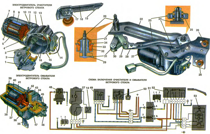
1. Output shaft of the geared motor. 2. Cover. 3. Driven gear. 4, 42. Brush holder. 5, 37. Electric motor housing. 6, 39. Armature shaft sleeve. 7, Felt ring. 8, 40. Anchor. 9. 38. Permanent magnet. 10. Gearbox mounting plate. 11. Crossbar. 12. Intermediate gear. 13. Block with limit switch contacts. 14. Thermal bimetallic fuse. 15. Gearbox housing. 16. Gear block. 17. Brush lever base. 18. Brush lever. 19. Lever rod. 20. Lever axis. 21. Lever axis fitting. 22. Wiper drive bracket. 23. Intermediate lever. 24. Crank. 25. Ball bearing. 26. Rubber bushing. 27. Windshield wiper motor. 28. Intermediate lever end. 29. Rocking lever. 30. Connecting rod. 31. Lever secured to axle 20. 32. Lever axle bushing. 33. Rubber bushing. 34. Windshield frame panel. 35. Electric motor mounting bracket. 36. Pump housing. 41. Outer magnetic circuit. 43. Pump cover. 44. Drive gear. 45. Suction pipe. 46. Delivery pipe. 47. Oil seal. 48. Windshield washer motor. 49. Ignition relay. 50. Ignition switch. 51. Fuse box. 52. Windshield wiper and washer switch. 53. Windshield wiper relay.
I. The order of numbering of plugs in the motor-reducer and windshield wiper relay blocks
II. Numbering order of the plugs in the windshield wiper switch socket
On Oka cars, an electric single-brush windshield wiper type 45.5205 is installed. It has two operating modes: continuous and intermittent, which are provided by the RS-514 relay.
The wiper drive is located under the hood in front of the windshield and is secured at three points. Drive bracket 22 is secured with nuts to the front shield, and nipple 21 of the lever axis is secured with a nut to the windshield frame panel. For shock absorption, rubber bushings 26 are installed in the mounting holes of bracket 22, and windshield frame panel 34 is clamped between two rubber bushings - lower 33 and upper.
The wiper consists of an electric motor 27 with a gearbox, a crank mechanism and a brush with a lever. The crank mechanism serves to convert the rotational motion of the gearbox shaft into a swinging motion of the brush. The crank 24, fixed on the gearbox shaft, when rotating through the intermediate lever 23 turns the lever 29, the second end of which rotates on the axis 20. The tip 28 of the lever 23 is connected through the connecting rod 30 to the lever 31 welded to the axis 20. Thus, the swinging motion is communicated to the lever 31 not directly from the lever 23, but through the connecting rod 30. Such a design of the mechanism provides a larger swinging angle of the lever 31. If the swinging angle of the lever 29 is approximately 90°, then the lever 31 rotates by 122°, which allows to increase the area of cleaning the windshield.
The axis 20 of the brush lever rotates in two metal-ceramic bushings pressed into the fitting 21 welded to the bracket 22. The bushings 32 of the axis are impregnated with oil, and therefore, when operating the vehicle, there is no need to lubricate this unit.
Lever 23 is connected to crank 24 by means of a double-row spherical ball bearing 25. Such a bearing allows the mechanism to operate reliably with some non-parallelism of the crank and lever. The lubricant contained in the bearing is sufficient for the entire service life of the vehicle.
The wiper blade is made of a pressed rubber strip of a special profile. The rubber strip is fixed in flexible metal holders mounted on a plastic reinforcement, which is attached to the lever 18 using a leash with a lock. In order for the brushes to clean the curved windshield well, they must be pressed tightly against the glass. This is ensured by a spring placed on the rod 19. Since the axis of rotation of the rod is located above the axis of rotation of the lever, the spring creates a torque pressing the brushes against the glass with a force of 6.3... 8.7 N (630...870 gf).
Windscreen wiper motor
Technical specifications:
- The rotation frequency of the gearbox shaft of the cleaner at the supply voltage of the electric motor of 14 V, the load torque of 1.47 Nm (0.15 kgf·m) and the ambient temperature of 25±10°C, min⁻¹, not less than — 50
- Current consumption at the above load moment, A, no more than - 3.5
The electric motor of the cleaner combines an electric motor and a gearbox in one unit. The electric motor is direct current, two-pole, two-brush, with excitation from permanent magnets. It has a steel, stamped in the form of a glass casing 5. Inside the casing, two permanent magnets 9 in the form of semicircles are fixed with spring holders riveted to the walls of the casing. The magnets are magnetized in such a way that their opposite poles are facing inside the casing. These magnets together with the casing form the stator of the electric motor.
The anchor 8 of the electric motor consists of a shaft, a core and a collector. The steel shaft of the anchor has a longitudinal knurling on the middle part, and a single-thread worm on the front end. The core, assembled from plates of electrical steel, is pressed onto the knurled part of the shaft. The anchor winding is laid in the grooves of the core, insulated with cardboard, the terminals of the sections of which are soldered to the copper plates of the collector. The collector has a plastic base and is pressed onto the shaft from the worm side.
The armature shaft rotates in a ball bearing pressed into the gearbox housing 15 and the metal-ceramic bushing 6 of the housing. The outer surface of the bushing is spherical, which allows it to self-install in the housing seat. A felt ring 7 is placed around the bushing. The bushing and felt are impregnated with oil. The ball bearing is also filled with grease. Therefore, it is not necessary to lubricate the electric motor during maintenance. The axial force acting on the armature shaft is perceived by the ball bearing, which is mounted on the armature shaft between two lock washers.
The electric motor housing is covered by the gearbox housing 15, which acts as a cover for the electric motor. The gearbox housing is cast from a light alloy and is attached to the electric motor housing with two screws. On the electric motor side, a crossbar 11 with two brush holders is riveted to the gearbox housing.
The gear wheels of the reducer are located in the housing 15. The rotation from the worm is transmitted to a block of two gear wheels 16 and an intermediate gear wheel 12, from which, in turn, the second block of gear wheels 16 rotates. The upper gear wheels transmit rotation to the driven gear wheel 3 with internal engagement, fixed on the output shaft 1 of the reducer. This shaft rotates in a metal-ceramic oil-impregnated bushing pressed into the cover 2. The gear ratio of the reducer is 1:75.
A plastic block 13 with three spring contacts of the limit switch is fixed on the outside of the gearbox housing. When the wiper is switched off, the switch ensures that the electric motor stops at the moment when the wiper brush is in the extreme lower position. The switch contacts are pressed against the shaped ring brass plate on the gear 3. To protect the electric motor from overloads in the event of the brush freezing to the glass, as well as in the case of high resistance to the movement of the brush or jamming in the wiper mechanism, a reusable thermal bimetallic fuse 14 is installed on the outside of the gearbox housing.
Windshield wiper motor operation
The wiper is activated by the right lever of the three-lever switch when the ignition is on. The lever has three positions: the initial upper (the cleaner is off), average (intermittent operation of the cleaner is enabled) and the extreme lower (continuous operation of the cleaner).
Intermittent operation is provided by relay 53 type RS-514. Current goes from the positive terminal of the battery or terminal 30 of the generator through contacts 87 and 30 of the ignition relay 49 to switch 52. Then, through the red wire, current goes to plug 2 of the relay and then through the relay winding. It is triggered, the upper (in the picture) relay contacts and current is supplied to plug "2" of the cleaner via the blue wire. The cleaner works.
At the same time, current flows through the winding of the breaker in relay 53 (in the picture above). This current heats up the breaker winding. The bimetallic breaker plate bends from heating, and the breaker contacts open, disconnecting the power supply to the relay winding. The relay anchor returns to its original position, and the upper (in the picture) the relay contacts open. The wiper motor stops.
Since the current no longer flows through the interrupter winding, it cools down together with the bimetallic plate. The plate takes its previous shape, and the interrupter contacts close, turning on the power supply to the relay winding. The cleaner turns on again. The described cycle is repeated again with a frequency of 9...17 times per minute.
During one cycle, the brush makes one double stroke and stops in the extreme lower position. At the initial moment of switching on the cleaner for intermittent operation (while the bimetallic plate of the breaker has not yet heated up) the brushes can make up to four continuous double strokes.
Continuous operation of the cleaner. Current flows from plug "5" of switch 52 via the blue wire to plug "2" of the cleaner's electric motor. The cleaner operates at a constant speed, and the brush swings at a frequency of 50...60 cycles per minute.
The wiper is switched off after the switch lever 52 is moved to its initial position. In this case, the current is supplied to the armature winding of the electric motor from plug "B" of fuse block 51 through the closed contacts of the limit switch of the electric motor. At the moment when the wiper brush reaches the lower position, the contacts of the limit switch open and the power supply to the armature winding is switched off. The armature of the wiper electric motor stops and the brush remains in the lower position.
Windshield washer motor
The electric motor, combined with the washer pump, is installed in the engine compartment on a bracket attached to the mudguard of the right wheel. The pump electric motor is a two-pole, two-brush, with excitation from permanent magnets. A steel ring 41 with a magnet 38, composed of two identical rings, is installed in the plastic housing 37. The steel ring is an external magnetic circuit and serves to strengthen the magnetic field of the magnet. The armature shaft rotates in two metal-ceramic bushings 39 impregnated with oil. Brush holders 42 are made as a single unit with the power supply plugs and are fastened with two screws to the housing 36 of the pump.
The plastic pump body 36 and cover 43 are fixed to the housing 37 of the electric motor. All these parts are pulled together with four screws through the steel bracket 35 of the electric motor mount. The washer pump consists of a pair of gear wheels made of bronze. The driving gear wheel 44 is mounted on the shaft of the electric motor and fixed to it with a pin key. The driven gear wheel rotates freely on the axis pressed into the pump housing. A rubber gasket is installed between the housing and the pump cover. The output end of the anchor shaft is sealed with a rubber gland 47 installed in the pump housing.
The washer motor is switched on when the ignition is on using the right lever of the three-lever switch 52. To do this, pull the lever towards you (non-fixed position of the lever). In the diagram of switch 52, the washer switch is shown on the left. Current for powering the electric motor is supplied from plug "A" of the fuse block.