




Contents: Headlights ↓ Front direction indicators ↓ Side direction indicators ↓ Ceiling lamp ↓ License plate lights ↓ Rear lights ↓ Rear fog light ↓
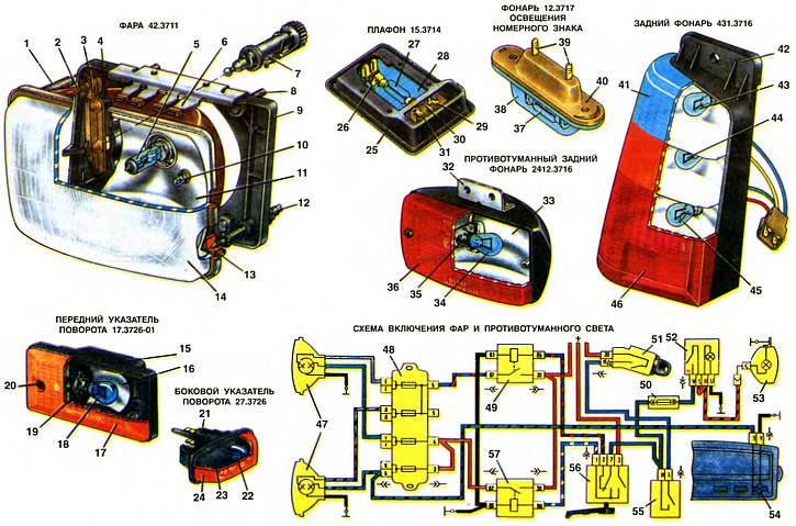
1. Tension spring. 2. Upper reflector holder. 3. Lever. 4. Vertical beam adjustment screw SV6TE. 5. AKG12-60+55 bulb. 6. Bracket. 7. Set screw. 8. Headlight mounting screw. 9. Headlight housing. 10. A12-4 parking light bulb. 11. Reflector. 12. Horizontal beam adjustment screw. 13. Lower reflector holder. 14. Headlight glass lens. 15. Front turn signal housing. 16. Reflector. 17. Front turn signal lens. 18. A12-21-3 bulb. 19. Bulb socket. 20. Diffuser mounting screw. 21. Plug holder with bulb socket. 22. Bulb A12-3-1. 23. Side direction indicator housing. 24. Indicator lens. 25. Lamp housing. 26. Post-plug for voltage supply and lamp mounting. 27. 37. Bulb AC 12-5. 28. Lamp lens. 29. Plug for connection to ground. 30. Switch. 31. Plug for connection to switches in the door pillars. 32. Lamp mounting bracket. 33, 40, 42. Lamp housing. 35. Lamp socket. 36, 38. Lamp lens. 39. Lamp holder plugs. 41. Three-color diffuser. 43. Bulb A12-21-3 for reversing light. 44. Lamp A12-21-3 direction indicator. 45. Lamp A12-21+5 brake signal and parking light. 46. Reflector. 47. Headlights. 48. Fuse box. 49. Relay for switching on low beam headlights. 50. 8 A fuse for protecting the fog light circuits. 51. Ignition switch. 52. Fog light switch. 53. Rear fog light. 54. Indicator lamp for high beam headlights. 55. Exterior lighting switch. 56. Headlight switch. 57. Relay for switching on high beam headlights.
Headlights
On Oka cars, headlights 42.3711 are used to illuminate the road at night. The design of the headlights provides an asymmetrical beam of low beam headlights that meets the requirements of the UNECE regulations (United Nations Economic Commission for Europe). Each headlight is attached to the front of the body by four 8 screws.
The low and high beams are switched by the left lower lever of the three-lever switch 56, mounted on the steering column. Voltage is supplied to it when the switch button 55 of the external lighting is fully pressed. In addition, it is possible to briefly turn on the high beam headlights (light signaling) when pulling the lever of switch 56 towards you in any position of switch key 55. This is ensured by the fact that the voltage to the contacts of the light signaling switch 56 is supplied directly from the power sources, bypassing the external lighting switch.
The filaments of the two headlamps consume a fairly significant current - about 8... 10 A. Therefore, in order to relieve the contacts of the headlamp switch and increase its service life, the headlamps are switched on not directly by switch 56, but through additional relays 49 and 57 of type 113.3747-10. They have powerful contacts and are installed in the passenger compartment on a bracket near the fuse box. Relay 49 switches on the low beam in both headlamps, and relay 57 - the high beam. As a result, only the supply current of the relay windings, not exceeding 0.2 A, flows through the contacts of switch 56.
The headlight has a plastic housing 9, made in the form of a frame. To increase the strength of the housing, a steel bracket 6 is attached to its upper part. At the front, it is attached to the housing at three points (two at the bottom and one at the top) an optical element is attached. At the bottom it rests on the heads of the adjusting screws 12, and at the top it is pulled to the socket of the lever 3 by the spring 1. The optical element is non-separable, consists of a reflector 11 and a diffuser 14 attached to it. From the back side, a headlamp lamp 5 is inserted into the reflector and below it - a socket with a side light bulb 10. On the flange of the bulb 5 there are projections that enter the corresponding grooves of the reflector. Therefore, the bulb is installed in it in a strictly defined position.
Reflector 11 headlights — steel rectangular. Its reflective surface has the shape of a large-diameter paraboloid, limited at the top and bottom by horizontal planes. The paraboloid concentrates the reflected rays of light into a beam, directing it along its axis if the thread of the lamp is in the focus of the paraboloid. Due to the increased horizontal diameter, the rectangular reflector provides large angles of dispersion of the light flux in the horizontal direction. Therefore, with low beam, the right side of the road is better illuminated and the light flux in the direction of the eyes of oncoming drivers is reduced, which increases traffic safety. To create a mirror surface, the reflective surface of the reflector is coated with varnish and then with a thin layer of aluminum. This coating reflects up to 90% of the light falling on it.
Diffuser 14 is made of colorless glass with a high degree of transparency. Its outer surface is smooth, and on the inner surface there is a system of prisms and lenses that turn parts of the light beam in the horizontal direction and concentrate the light flow at the most important points of the road.
Lamp 5 of the headlight is halogen, its bulb contains iodine vapor. Halogen lamps have increased luminous efficiency and are almost twice as durable as conventional lamps. In addition, the luminous efficiency of halogen lamps decreases little over time, since they do not have tungsten deposition on the inner walls of the lamp bulb and it does not darken. The process that occurs in a halogen lamp is as follows. When the lamp burns, microparticles of tungsten evaporate from the filament and are deposited on the walls of the lamp. Iodine vapor comes into contact with this deposited tungsten, and at a temperature of about 600°C, iodide tungsten is formed. This compound is unstable at high temperatures and, getting into the zone of the hot filament, decomposes into iodine and tungsten, which is deposited on the filament, and iodine moves to the walls of the bulb. Thus, in the switched on lamp, there is a constant transfer of tungsten from the walls to the filament. Therefore, the walls of the flask remain clean, the thread thins more slowly and the durability of the pump increases.
When replacing halogen lamps, you must be careful and handle the lamp with gloves or a handkerchief to avoid leaving greasy fingerprints on the lamp glass. If there are such fingerprints on the lamp, you must remove them with alcohol. Grease stains cause the lamp glass to darken because it heats up to high temperatures. As a result, the lamp's light output decreases, it overheats and fails faster.
The lamp has two tungsten filaments: one (55 W) for low beam and the other (60 W) for high beam. The high beam filament is in the focus of the reflector, and therefore the high beam rays are collected into a narrow beam directed almost parallel to the road and illuminating it well at the maximum distance from the car. The low beam filament is brought forward from the focus of the reflector and covered from below by a special metal screen. This is done in order to limit the spread of low beam upward.
If you direct the low beam beam at a wall, the light spot will have the shape of an ellipse with the upper half cut off. In the left part of the spot, the upper boundary of the illuminated area will pass exactly along the horizontal axis of the ellipse, and in the right part - along the line emanating upward from the center of the ellipse at an angle of 15° to its horizontal axis. This shape of the light beam provides good illumination of the road in front of the car (especially its right side and the shoulder), and the possibility of blinding oncoming drivers is reduced.
The direction of the light beam of the headlight in the vertical plane can be adjusted by screw 4, and in the horizontal plane - by screw 12. On the right lower side of the headlight there is another screw, similar to screw 12. This screw, if necessary, adjusts the direction of the light beam simultaneously in the horizontal and vertical planes. When turning screw 12, the left edge of the reflector moves forward or backward, and it rotates relative to the ball heads of the holder 2 and the right lower adjusting screw. When turning screw 4, the reflector rotates relative to the lower screws 12 via lever 3.
The headlight housing has a socket into which the adjusting screw 7 is inserted. This screw can be used to adjust the direction of the headlight beam depending on the vehicle load. It is customary to adjust the headlight beam with a load of 75 kg on the driver's seat and with the head of the adjusting screw turned counterclockwise until it stops. At full load, the rear of the vehicle is lowered and, in order to maintain the previous direction of the beam, the head of the adjusting screw 7 is turned clockwise to the extreme right position
Front direction indicators
On Oka cars, two identical front direction indicators 17.3726-01 are used. They are located below the headlights and are attached to the front bumper with two screws. The indicators have a plastic housing 15, to which a lamp socket 19 and a metal reflector 16 are riveted inside. An orange plastic diffuser 17 is attached to the housing with two screws 20.
[The text is copied from the online resource: VAZbook.ru]
Side direction indicators
Side direction indicators 27.3726 (same on right and left) are attached to the front fenders of the car with two elastic latches made in one piece with the body. A PVC seal is installed under the indicator. To remove the indicator, it is necessary to insert a screwdriver or a metal ruler between the seal and the fender from the front side of the car and press the latch.
The housing 23 of the indicator is made of plastic. A plastic orange diffuser 24 is also welded to the housing using ultrasonic welding. The holder 21 of the plugs with the lamp socket is inserted into the housing from the back of the indicator.
Ceiling lamp
To illuminate the interior of the Oka cars, a lampshade 15.3714 is installed. It is attached to the roof of the car with two self-tapping screws. The lampshade has a plastic housing 25 and a transparent plastic diffuser 28, on which a switch 30 and a plug 26 with a contact for attaching the lamp are installed. Voltage is supplied to plug 26. Plug 29 is connected directly to ground, and plug 31 is connected through switches in the door pillars. When the doors are opened, these switches close plug 31 to ground, and the lamp lights up. With the doors closed, the lamp can be turned on by switch 30 of the lampshade.
License plate lights
Two license plate lights 12.3717 are installed in the middle part of the rear bumper above the license plate and are attached to the bumper with two screws. Two holders-plugs 39 for attaching the lamp and connecting the wire tips are installed in the plastic housing 40 of the light. The colorless plastic diffuser 38 is attached to the housing with the help of a spring protrusion on the housing.
Rear lights
Rear lights serve to indicate the dimensions of the car at night, to indicate a turn, to signal the brakes and to signal and illuminate the roads when the car is moving in reverse. Rear lights are divided into right 43 3716 and left 431 3716. The left light is made a mirror image of the right. The light is attached to the outer panel of the rear of the car at the top with a screw, and at the bottom it is hooked with the protrusion of its body onto the edge of the socket in the body.
The body of the 42 lamp is made of metallized plastic and is divided by partitions into four chambers. In the upper chamber is the lamp 43 of the reversing light, below it is the lamp 44 of the turn signal, and at the bottom is the two-filament lamp 45 of the brake signal (thread 21 W) and side lights (5 W filament). A three-color plastic diffuser 41 is welded to the housing: red - in the area of the brake signal chambers (and side lights), orange - in the direction indicator camera area and colorless - in the reversing light camera area. At the bottom, a reflector 46 is welded to the diffuser - a light-signaling device that reflects the light falling on it.
Rear fog light
On some Oka cars, a rear fog lamp 2412.3716 is installed. It is attached to the left lower side of the rear bumper with two screws. The housing 33 and the diffuser 36 are made of plastic and connected with two screws. The lamp socket 35 and the mounting bracket 32 are riveted to the housing.
The rear fog light is switched on by switch 52, located on the instrument panel. Voltage is supplied to it when the switch button 55 of the external lighting is fully pressed, i.e. when the headlights are on.