
Inspect the cylinder head. The bearings under the camshaft journals and in the holes for the valve lifters must not be scratched or damaged. Cracks in any places of the cylinder head are not allowed. If you suspect that coolant has entered the oil, check the tightness of the cylinder head.
To check the tightness, close the holes of the cooling jacket with plugs and pump water under a pressure of 0.5 MPa with a pump. No water leakage should be observed within 2 minutes. You can check the tightness of the cylinder head with compressed air, for which they close the holes of the cooling jacket with plugs, lower the cylinder head into a bath of water heated to 60-80°C, and let it warm up for 5 minutes. Then compressed air is fed into the head at a pressure of 0.15-0.2 MPa. Within 1-1.5 minutes, air etching from the cylinder head should not be observed.
Valve seats
On the working chamfers of saddles (pic. 59) the valve contact area must be free of pitting, corrosion or other damage. Minor damage to the surface of the working chamfers is eliminated by grinding with a grinder or by hand, removing as little metal as possible.
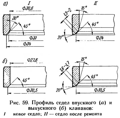
Before grinding, the chamfers are cleaned of cold hardening and carbon deposits, for which a centering rod A.94059 is inserted into the valve guide bushing and a 15°chamfer is milled with a cutter A.94092 for the intake valve seat or A.94003 for the exhaust valve. The cutters are put on the spindle A.94058. Then a 2-0°chamfer is milled with a cutter A.94031 for the intake valve seat or A.94101 for the exhaust valve.
After cleaning the chamfers, a 45°chamfer is ground, ensuring the chamfer width according to fig. 59 and base diameters 34 and 30.5 mm. Chamfers are ground with conical wheels A.94100 for intake valve seats and A.94078 for exhaust. Circles are put on the spindle A.94069. At the moment the wheel contacts the seat, the grinder must be turned off, otherwise vibration will occur and the bevel will be incorrect.
After grinding, the seats and channels of the cylinder head are thoroughly washed and blown with compressed air.
Valves
Remove carbon deposits from valves. Check if the rod is deformed (rod curvature 0.015 mm) and there are no cracks on the valve head. The damaged valve is replaced.
Check the condition of the working chamfer of the valve. In case of minor damage, it can be sanded, maintaining a chamfer angle of 45°30'±5'. In this case, the distances from the lower plane of the valve head to the base diameters (∅ 34 and ∅ 30.5 mm) should be 1.3-1.5 mm for the intake and 1.8-2.0 mm for the exhaust valve.
Valve guides
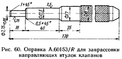
Check the clearance between the valve guides and the valve stems by measuring the valve stem diameter and the valve stem bore. The clearance value must match the data tab. 2. If the clearance is greater than the allowable value, replace the valve. If excessive clearance cannot be corrected by valve replacement alone, replace the guide bushing as well. For this operation use mandrel A.60153/R (pic. 60), pressing the bushings with the retaining ring on until it stops against the body of the cylinder head.
As spare parts, guide bushings are supplied with an outer diameter increased by 0.02 mm and an allowance for the inner diameter. Therefore, after pressing, drill holes in the guide bushings with reamers (A.90310/1 - for inlet valve bushings and A.90310/2 - for exhaust valve bushings). Then check the tightness of the valves and, if necessary, grind the valves to the seats.
Oil deflector caps for guide bushings
At oil seals, delamination of rubber from fittings, cracks and excessive wear of the working edge are not allowed. When repairing the engine, it is recommended to always replace the oil seals with new ones.
It is necessary to replace damaged caps on the removed cylinder head so as not to bend the valve stems. To press the caps, use the mandrel 47.7853. 4016 (see fig. 47).
Springs and pushrods
Springs are checked for elasticity and cracks. The elasticity of the valve springs is checked by the length of the spring in the free state (45.2 mm - external and 34.1 mm - internal) and under load: (255,1±16,7) H and (453,2±23,5) H for outer spring (while the length should be respectively 33.7 and 24.7 mm); (88,3±7,8) Neither (269,8±14,7) H for internal (while the length is respectively 29.7 and 20.7 mm).
At valve lifters, check the condition of the working surface. It should not have nicks or scratches. In case of damage, the pusher is replaced.
Adjusting washers, cylinder head bolts
The working surfaces of the washers must be smooth, without nicks, scratches and scuffs. They should not have stepped or one-sided wear, metal rubbing. Concentric run-in marks with camshaft cams are allowed.
With repeated use of the cylinder head bolts, they are pulled out. Therefore, it is checked whether the length of the bolt exceeds 135.5 mm (without taking into account the height of the bolt head), and if it is more, then replace the bolt with a new one.