

Carburetor in a small block combined several systems (idling, transitional, main dosing) and devices (accelerator pump, econostat, economizer, starting), the purpose of which is to create combustible mixtures corresponding to one or another mode of engine operation. There are many modes - starting the engine, idling, medium loads, full loads - and each of these modes requires its own combustible mixture.
It should be recalled that running the engine on a lean mixture is undesirable, as engine power drops. If you lean the mixture even more, the power will decrease significantly, the engine will overheat and, despite the fact that the mixture is lean, gasoline will be consumed more than normal. When running on a lean mixture, flashes occur in the carburetor and it starts «sneeze». The engine also does not work well with a re-enriched mixture. Are distributed «shots», clouds of smoke come out of the muffler. And inside the cylinders at this time the following happens: unburned fuel particles create soot, coked oil particles and varnish deposits, together with soot, contribute to overheating of engine parts.
Unburned fuel, flowing down the cylinder mirror, washes away the oil film, and this, in turn, increases the wear of rubbing parts.
What mixture provides optimal conditions for engine operation? Experience suggests that a somewhat lean mixture will be most beneficial for normal operating conditions (most economical).
In difficult road conditions, where an excess of power is needed, the mixture should be slightly enriched.
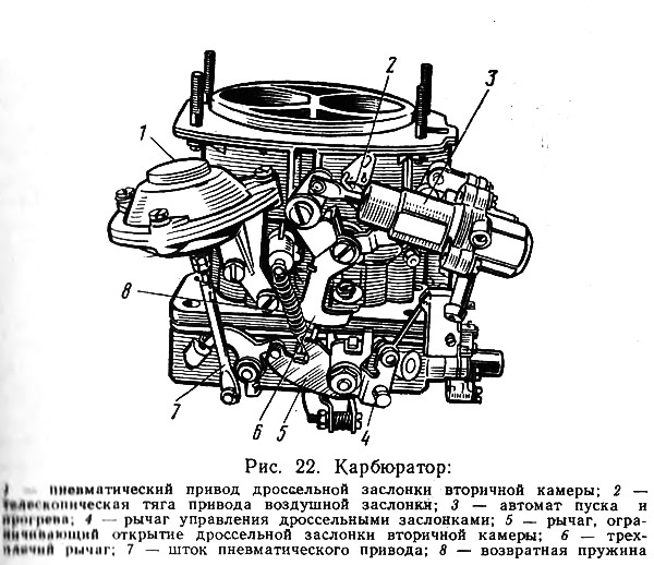
On VAZ cars, two-chamber carburetors are installed (pic. 22) with sequential throttle opening. Carburetor «Ozone» has a pneumatic drive of 1 throttle valve of the secondary chamber and can be equipped with either an independent idle system (abbreviated ASHH), or a set of ACXH and EPHH, i.e. forced idle economizer. The set of these devices is called «Cascade».
Most experienced drivers use the engine as a brake. With long descents and in close traffic, this method of braking is quite justified. One bad thing - gasoline flies into the wind.
In the PXX mode (forced idle) - this is the name of elementary engine braking, the latter does not need gasoline. In order to interrupt the fuel supply at the right time, a forced idle economizer was developed. The automation is controlled by special sensors that respond to the position of the throttle valve and the speed of rotation of the crankshaft.
Carburetor «Ozone» thanks to the adjustment of the dosing systems of the primary chamber, it is significantly more economical than its predecessors. System «Cascade» allows you to make fuel consumption even more economical, and the overall reduction in consumption can be 1-3 liters per 100 km.
Although carburetors «Ozone» designed specifically for installation on cars VAZ-2105 and VAZ-2107, they can be installed without any alterations on VAZs of all models and any year of manufacture. DVAZ-2105 (this is another name for a carburetor manufactured by the Dimitrovograd Aggregate Plant) designed for cars VAZ-2101, VAZ-2102, VAZ-21011, VAZ-2105, and DAZ-2107 for cars VAZ-2103, VAZ-2106, VAZ-2107 and VAZ-2121.
In connection with the advent of the new carburetor, a new vacuum ignition distributor was also developed, which automatically changes the ignition timing depending on the engine load.
However, there are cars with old carburetors and distributors in operation, and, naturally, some motorists have a desire to equip the engine with modern devices. The designers took this into account. Here are some combinations that can be used:
- vacuum distributor and carburetor designed to work with it;
- carburetor «Ozone» and distributor of the old model;
- new distributor and old carburetor. In this case, in order to avoid increased fuel consumption, it is necessary to reduce the performance of the jet of the main metering system.
If on the carburetors of the previous «Ozone» generations, any of the motorists could do the adjustment of the engine idle speed, as soon as he considered it necessary, then on «Ozone» the plant sharply limited this need and possibility. Thus, the motorist is given only a field of activity for control. Intervention is admissible only at an obvious excessive consumption of fuel.
If adjustment is necessary, remove screws 1 and 2 (pic. 23), break their heads, remove bushings 4 and 5 and tighten new screws; warm up the engine (coolant temperature must be at least 80-90°C); Check if the ignition timing and valve clearances are set correctly. For objectivity of adjustment it is necessary to use a gas analyzer.
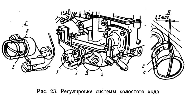
With screw 2, it is necessary to set the maximum speed of the crankshaft, with screw 1, bring the speed of the crankshaft to 850-900 rpm. In this position of the screw 1 again screw 2 to ensure the content of CO in the exhaust gases up to 1-1.5%. During the adjustment process, the crankshaft speed may change, and therefore the screw 1 restores the number of revolutions to 850-900.
After completing the adjustment work, press the restrictive bushings onto the screws (such red bushings, unlike blue factory ones, are available at service stations) so that the bushing stop 4 is to the right of the stop 3 at a distance of no more than 1.5 mm, and the stop on the bushing 5 is at an equal distance to the left and right of the stop 6.
It is known that the main advantage of the new generation of carburetors is their efficiency, which is achieved mainly by using a pneumatic actuator of the throttle valve of the secondary chamber.
It must be remembered that the pneumatic drive is activated when the loads are high. So, it was experimentally established that on a VAZ-2103 car with two passengers on board and 100-120 kg of cargo in the trunk, the throttle valve in the secondary chamber opens in third gear at a speed of 90 km/h, and in fourth gear in the speed range from 100 to 120 km/h
It is clear that when driving in a city, such a speed cannot be developed, the secondary chamber does not enter into operation, and fuel consumption should be optimal. If excessive fuel consumption is detected, then the conclusion suggests itself: there are malfunctions in the drive of the secondary chamber.
The most likely cause of excessive fuel consumption is the loose closing of the throttle valve of the secondary chamber at low loads. In this case, often «guilty» automation, or rather its vulnerability. Automation and dirt are incompatible concepts. It is the dust and dirt deposited on the drive parts that distort «accuracy» automation. Dirt makes it difficult to rotate the throttle shaft in the body. Sand and dust that have settled on the springs between the levers make it difficult to move them together.
It happens that small and precise parts of the drive are deformed by the careless movement of the assembler or repairman. As a result, the shutter of the secondary chamber freezes and there is a clear deterioration in the operation of the engine with a significant excessive consumption of fuel.
Recently, devices have appeared on sale with which you can quite accurately adjust the operation of the carburetor. Some motorists, for example, speak well of the X-1 quality indicator. The indicator is screwed in instead of one of the candles. In the indicator mirror you can see if the mixture burns well. The bright blue color of the flame indicates that the carburetor is putting out a good mixture. An orange color of the flame indicates that an adjustment is needed.
carburetors «Zhiguli» Very «do not like», when the fuel level in the float chamber rises above normal. This level must be checked and, if necessary, adjusted. It also makes sense to perform this operation because as the level increases, fuel consumption increases markedly. Especially «sensitive» to increase the level of fuel carburetors «Ozone». Even minor deviations from the norm can cause unstable engine idling due to the ejection of fuel droplets from the atomizer into the diffuser of the primary chamber.
VAZ car carburetors can be disassembled in stages, in parts. So, to check and adjust the fuel level in the float chamber, it is only necessary to remove the carburetor cover. Before the cover, remove the air cleaner, disconnect the starter drive, disconnect the throttle actuator by removing the plastic hinge from the ball pin of the primary chamber throttle actuator lever, disconnect the fuel line and the crankcase ventilation pipe.
To remove the carburetor cover, you need to prepare a clean table and good light. Then remove the spring 8 (see fig. 22) throttle actuator lever of the secondary chamber, disconnect the pneumatic drive rod 7. After compressing the telescopic link spring 2, separate it from the lever 6'. After completing these operations, you can remove the carburetor cover by first unscrewing the screws.
Removed cover 1 (pic. 24) wash the carburetor in gasoline, blow it with compressed air, check the condition of the filter 3. Clean off dirt, oil and check the condition of the cover, all parts and assemblies located on it.
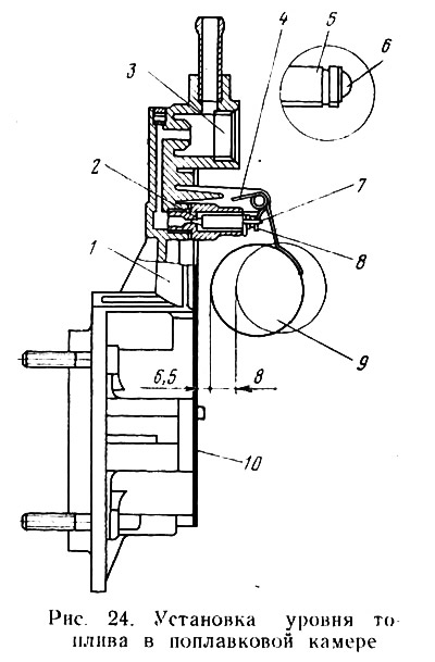
After completing the work, take an interest in the condition of the mating surfaces, gasket 10, which should not be damaged, hardened; float 9, which must be tight, without dents or cracks. Before installing the carburetor cover, it is necessary to check whether the float moves freely on the axis.
Violation of the fuel level in the float chamber depends mainly on the state of the float 9 and the distance between the float body and the carburetor cover 1. The float works normally if the distance between it and the edge of the carburetor cover is within 6.5±0.25 mm. The easiest way to control this size is with a caliber. When measuring, the carburetor housing cover must be held vertically. At this time, the tongue 8 of the float should touch the ball surface 6 of the needle valve 5. The specified size is provided by bending the tongue. In this case, it is desirable to maintain the perpendicularity of the axis of the needle valve and the support pad of the tongue. The full stroke of the float should be in the range of 7.75-8.25 mm, and this is achieved by bending the stop 4.
After completing the adjustment, it is useful to make sure that the valve needle yoke 7 does not interfere with the free movement of the float. When adjusting the fuel level in the float chamber, be consistent to the end: check the needle valve itself. It is considered serviceable if it meets two conditions: it is easy to move (without jamming) in his nest, up by the influence of the float and down by natural laws; does not leak fuel when closed. To replace a defective needle valve, it is necessary to remove the float shaft, remove the float, needle valve and at the same time replace the valve seat 2, using a 10 mm wrench for this purpose. While the cover is removed, blow through all the carburetor jets, channels and cavities with compressed air. Having done all this, put the carburetor cover back in place and tighten the screws.
When dealing with a carburetor, at the same time check how it itself is mounted on the engine; and if necessary, tighten the nuts, and with a screwdriver - fasten the cover (see fig. 22) carburetor starting device, start and warm-up automatic cover. Reinstall the damper control rods and air cleaner.
Usually, when the jets are blown with compressed air, the fuel pump filter is also processed. To do this, unscrew the bolt securing the fuel pump cover with a 10 mm wrench, remove the cover together with the washer and filter. The filter and the cavity under it are blown with compressed air, and everything is put in place. In order not to form an air lock, after disassembling the fuel pump, it is imperative to pump up fuel using a manual drive.