
Install the cylinder head on the stand, remove the carburetor throttle drive rod, unscrew the nuts and remove the carburetor with the gasket, and then the intake pipe.
Remove the spark torque sensor and the outlet pipe of the engine cooling jacket. Remove the coolant temperature gauge and spark plugs.
Unscrew the nuts and remove the fuel pump with gaskets, spacer and pusher. Disconnect the auxiliary unit housing from the cylinder head.
Remove the camshaft bearing housing. Remove the camshaft from the cylinder head bearings and remove the oil seal from it.
Take out from the holes of the cylinder head pushers 11 (pic. 46) valves with shims 10. Release the valves from crackers 9 by compressing the valve springs with tool 67.7823.9505 (pic. 47). Remove the springs with plates. Turn the cylinder head and remove the valves from the underside. Remove the oil seals from the guide bushings and spring washers.
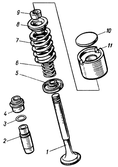
Pic. 46. Valve mechanism details: 1 - valve; 2 - guide sleeve; 3 - retaining ring; 4 - oil deflector cap; 5 — a basic washer of springs; 6 - internal spring; 7 - outer spring; 8 - a plate of springs; 9 - crackers; 10 - adjusting washer; 11 - pusher.
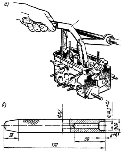
Pic. 47. Equipment for disassembly and assembly of the valve mechanism: a - fixture 67.7823.9505 for compressing springs; b - mandrel 41.7853 4016 for installing oil seals.
When assembling, the spring washers are installed. Lubricate the valves and new valve stem seals with engine oil (old ones are not allowed). Using mandrel 41.7853.4016, the caps are pressed onto the guide bushings. Insert the valves into the guide bushings, install the springs and spring plates.
Compressing the springs with tool 67.7823.9505 (see fig. 47), install the valve cotters. Insert valve tappets with shims into the holes of the cylinder head.
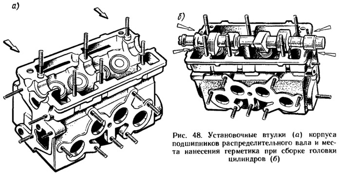
Check if the locating sleeves of the camshaft bearing housings are in place (put on studs in fig. 48, a). They clean the mating surfaces of the cylinder head and bearing housing from the remnants of the old gasket, dirt and oil.
Using the guide bush from the mandrel kit 67.7853.9580 (see fig. 22) put a new oil seal on the camshaft, lubricating its end with engine oil. Lubricate the bearing journals and camshaft cams with engine oil and place it in the cylinder head bearings in such a position that the cams of the first cylinder are directed upwards, and the second downwards.
on the surface of the cylinder head. mating with the bearing housings, in the area of the extreme bearings of the camshaft, a sealant of the SUPER THREE BOND type No. 50 or equivalent domestically produced sealant type KLT-75T (pic. 48b). It must be borne in mind that it is allowed to start the engine no earlier than 1 hour after applying the sealant. The exposure time of the sealant in air is allowed no more than 10-12 minutes.
Install the bearing housing and tighten the nuts of its fastening in two steps:
- 1st reception - pre-tighten the nuts in the sequence indicated on rice. 21, until the surfaces of the bearing housing come into contact with the cylinder head, making sure that the mounting sleeves of the housing freely enter their sockets;
- 2nd reception - finally tighten the nuts with a torque of 21.6 N·m in the same sequence.
Immediately after tightening the bearing housing fastening nuts, carefully remove the sealant residue squeezed out of the gaps during tightening in areas mating with the cylinder head cover gasket and with the auxiliary unit housing. Non-removed cured sealant residues in these areas will cause oil to leak through the seals.
Install the outlet pipe of the cooling jacket with a gasket and the housing of auxiliary units with a sealing ring. In accordance with the instructions of Sec. «Fuel pump» install a heat-insulating spacer with gaskets, a pusher and a fuel pump. Install spark torque sensor (see sect. «Engine assembly»).
Put a gasket on the cylinder head studs and install the intake pipe. Install the carburetor with gasket and carburetor throttle drive rod. Close the carburetor with a technological plug. Spark plugs and a coolant temperature indicator sensor are wrapped in the cylinder head.
The clearances in the valve mechanism are adjusted after the cylinder head is installed on the engine.