
On cars 21011 and 21013, the external design of the instrument cluster is somewhat different from the instrument cluster of car 2101, but its device is the same.
The instrument cluster is installed in the instrument panel nest and secured with two spring holders located on the sides.
Coolant temperature gauge
Magnetoelectric, type UK191, is used in conjunction with the TM106 sensor. There are two risks and a red zone on the pointer scale. The first risk corresponds to 30°C, the second to 60°C, and the beginning of the red (dangerous) zones - 108°С.
The pointer operates on the principle of a logometer. The total magnetic flux created by two coils located at an angle of 90 0 acts on a permanent magnet mounted on the arrow axis. Depending on the strength of the current flowing through the windings of the coils, the arrow magnet deviates to the appropriate position.
If the resistance of the sensor is 1000-5000 ohms, the pointer should be at the beginning of the scale, and if the resistance is 98-110 ohms - at the beginning of the red zone (at pointer temperature 20°С).
Fuel gauge
Type UB191, like the coolant temperature gauge, is magnetoelectric and has the same design and principle of operation. It differs in winding data and some other details. The pointer is used in tandem with a BM150 or BM154 type sensor (on vehicles 2102 and 21021). With a sensor resistance of 285-335 ohms, the arrow should be at the beginning of the scale, with a resistance of 100-135 ohms - in the middle of the scale, and with a sensor resistance of 7-25 ohms - it should deviate to the end of the scale (mark 4/4).
Speedometer
Type SP 191, consists of a speed indicator (km/h) and total trip counter (km), passed by the car. The speedometer scale has divisions from zero to 160 km / h every 10 km / h, as well as three red risks corresponding to speeds of 37; 62 and 96 km/h. These risks indicate the maximum speeds in I, II and III gears.
The speedometer mechanisms are driven by a flexible shaft from a gearbox mounted on the rear cover of the gearbox. The torque to drive the speedometer does not exceed 50 gsm.
The calibration data of the speedometer are as follows: at a drive shaft speed of 250 rpm, the speedometer readings should correspond to 14 ÷ 16.5 km / h, at 500 - 30-32.5; at 750 - 45-48; at 1000 - 60-63.5; at 1250 - 75-79; at 1500 - 90-94.5; at 1750 - 105-110; at 2000 - 120-125.5; at 2250 - 135-141; at 2500 rpm - 150-156.5 km / h.
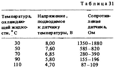
Coolant Temperature Gauge Sensor
Type TM106, wrapped in the cylinder head on the left side of the engine. A thermistor is installed in the sensor, which changes its electrical resistance depending on the temperature of the coolant. The data for checking the sensor are given in Table. 31.
Fuel gauge sensor
Type BM150 (BM154 for cars 2102 and 21021), installed in the fuel tank. The sensor has a variable resistor made of nichrome wire. The moving contact of the resistor is controlled by a float lever. At the short end of this lever there is also a movable contact that turns on the fuel reserve warning lamp if 4-6.5 liters remain in the tank (5-7.5 liters for cars 2102 and 21021) gasoline.
With an empty tank, the resistance of the sensor should be 315-345 ohms, with a half-filled tank, 108-128 ohms, and with a full tank, no more than 7 ohms.
Oil pressure warning light sensor
Type MM120, screwed into the engine block on the left side. The sensor has a diaphragm, which is affected by oil pressure. The diaphragm is connected with a moving contact. If the pressure in the engine lubrication system is below 0.4-0.8 kgf / cm2, then the movable contact is pressed against the fixed contact by a spring, the power supply circuit of the control lamp is closed and the lamp is on. As soon as the oil pressure exceeds 0.4-0.8 kgf / cm2, it bends the diaphragm and, overcoming the resistance of the spring, pushes the movable contact from the fixed contact with the pusher. The control lamp power supply circuit opens and the lamp goes out.
Until 1976, exhaust sensors worked at a pressure of 0.2–0.6 kgf/cm2.