




The car is equipped with a single-disk, dry clutch with a central diaphragm spring and hydraulic drive. The clutch has one driven disk, and its driven and leading parts are pressed against each other by a central spring. The clutch transmits torque from the engine due to dry friction forces.
The force from the pedal to the clutch release fork is transmitted through fluid.
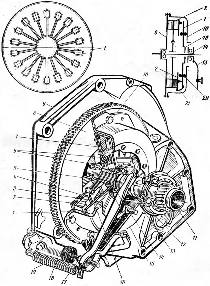
Fig. 26. Clutch:
1 - central pressure spring: 2 - driven disk; 3 - friction lining; 4 - disk; 5 - hub; 6 - torsional vibration damper; 7 - pressure plate; 8 - flywheel: 9 - clutch housing; 10 - bolt; 11 - primary shaft of the gearbox; 12 - Clutch release sleeve; 13 - clutch release fork; 14 - clutch release bearing; 15 - thrust flange of the pressure spring; 16 - clutch housing; 17 - adjusting nut; 18 - clutch slave cylinder; 19 - fork spring; 20 - support ring; 21 - retainer.
The clutch (Fig. 26) includes: driving parts (flywheel 8, casing 16, pressure plate 7), slaves (slave disk 2) and on/off details (spring 1, clutch 12, bearing 14). The casing 16, the pressure plate 7 and the pressure spring 1 are a non-separable unit which is fastened to the flywheel 8 with bolts 10. Between the flywheel and the pressure plate on the splines of the drive shaft 11 of the gearbox, the driven disk 2 is installed, consisting of a hub 5, a steel split disk 4 and friction linings 3. The driven disk is equipped with a spring-friction damper of torsional vibrations 6, which ensures an elastic connection between the hub 5 and the disk 4, as well as damping of torsional vibrations. The diaphragm spring 1, in a free state, has the form of a truncated cone with radial slots extending from its inner edge. The radial slots form eighteen petals, which are elastic release levers. The elasticity of the levers helps to ensure smooth operation of the clutch. Spring 1 is secured to clutch housing 16 by means of rivets and two support rings 20. Its outer edge, in contact with pressure plate 7, transmits force from the spring to the pressure plate.
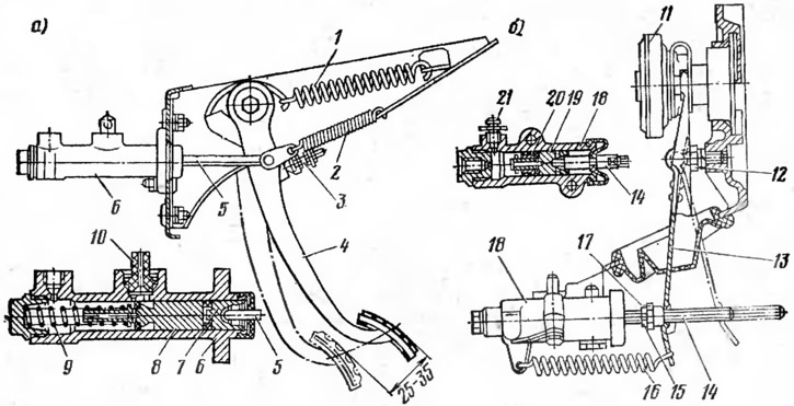
Fig. 27. Clutch drive:
a - pedal and master cylinder; b - working cylinder and fork:
1 - servo spring; 2 - pedal spring; 3 - pedal travel limiter; 4 - pedal; 5, 14 - pushers; 6, 18 - cylinder bodies; 7 - pusher piston; 8, 19 - cylinder pistons; 9, 20 - piston springs; 10, 21 - nipples; 11 - clutch release bearing; 12 - ball joint; 13 - clutch release fork; 15 - lock nut; 16 - fork spring; 17 - adjusting nut.
The hydraulic clutch drive (Fig. 27) includes: pedal 4, master cylinder and its reservoir, slave cylinder, connecting pipelines and clutch release fork 13. When the clutch is released, the force from pedal 4 is transmitted through pusher 5 of the master cylinder to pistons 7 and 8, which displace fluid into the pipeline and slave cylinder. Piston 19 of the slave cylinder through rod 14 turns clutch release fork 13, which moves the coupling with bearing 11. The bearing through thrust flange 15 (see fig. 26) moves the inner edge of spring 1 towards flywheel 8. The spring bends in the opposite direction, its outer edge through the clamps 21 moves the pressure plate 7 away from the driven disk 2, and the clutch disengages - does not transmit torque from the engine to the transmission. When the clutch pedal is released, under the action of spring 1, the pressure plate presses the driven disk to the flywheel, and the clutch engages - transmits torque to the transmission. At the same time, all other parts of the clutch and its drive return to their original position under the action of the springs: the release fork, the pistons of the master and slave cylinders and the clutch pedal.
Spring 1 (see fig. 27), connected to the clutch pedal, reduces the force on the pedal when disengaging the clutch. The free travel of the pedal, equal to 25-35 mm and corresponding to a gap of 2 mm between the end of the bearing 11 of the clutch release and the thrust flange of the central pressure spring, is adjusted by nut 17. The free travel of the pedal is necessary for full engagement of the clutch and preventing wear and failure of the clutch release bearing.
The information can be read on the website www.VAZbook.ru