
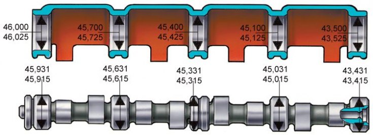
The main dimensions of the camshaft and bores in the camshaft bearing housing
Cylinder head section by exhaust valve
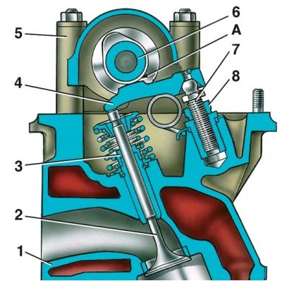
1 – a head of cylinders; 2 - exhaust valve; 3 - oil deflector cap; 4 – valve lever; 5 – the case of bearings of a camshaft; 6 - camshaft; 7 - adjusting bolt; 8 - bolt locknut; A - the gap between the lever and the camshaft cam
Diagram of the camshaft drive mechanism and auxiliary bodies
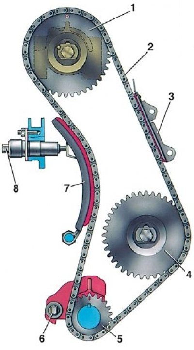
1 - camshaft sprocket; 2 - chain; 3 - chain damper; 4 - an asterisk of the oil pump drive shaft; 5 - crankshaft sprocket; 6 - restrictive finger; 7 - tensioner shoe; 8 - chain tensioner
Chain tensioner section
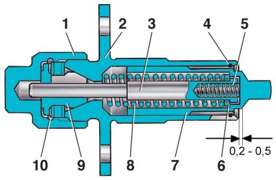
1 - cap nut; 2 - tensioner housing; 3 - rod; 4 - spring ring; 5 - plunger spring; 6 - washer; 7 - plunger; 8 - spring; 9 - cracker; 10 - spring ring
Camshaft
Camshaft - cast iron, cast, rotates on five bearings in a cast aluminum bearing housing mounted on the cylinder head. It is kept from axial movements by a thrust flange placed in the groove of the front bearing journal of the shaft. The main dimensions of the camshaft and camshaft bearing housing are given in fig. The main dimensions of the camshaft and bores in the camshaft bearing housing.
On VAZ vehicles until April 1982, camshafts with cams and bearing journals hardened by high-frequency currents were installed. From April 1982, nitrided camshafts were installed. Since 1984, the year of manufacture has been marked on the shafts. Since 1985, camshafts with cam cams have been installed; these shafts have a distinctive hex collar between the 3rd and 4th jaws.
The valves are actuated by the camshaft via short steel levers 4 (see fig. Cylinder head section by exhaust valve). The levers swing on the spherical head of the bolt 7, which regulates the gap A between the camshaft cams and the levers.
Camshaft drive
The camshaft is driven from the drive sprocket 5 (see fig. Diagram of the camshaft drive mechanism and auxiliary bodies) crankshaft with a double-row roller chain. The same chain drives the sprocket 4 of the oil pump drive shaft. The chain drive has a semi-automatic tensioner 8 with a shoe 7 and a chain damper 3 with rubber pads. A restrictive pin 6 is installed at the bottom of the cylinder block, which prevents the chain from falling into the crankcase when the camshaft sprocket is removed from the car.
The tensioner consists of a body 2 (see fig. Chain tensioner section), a rod 3 with two springs, a plunger 7 and a cap nut 1 with a clamping cracker 9, which is fixed in the nut with a retaining ring. The plunger is kept from falling out of the housing by a retaining ring 4.