
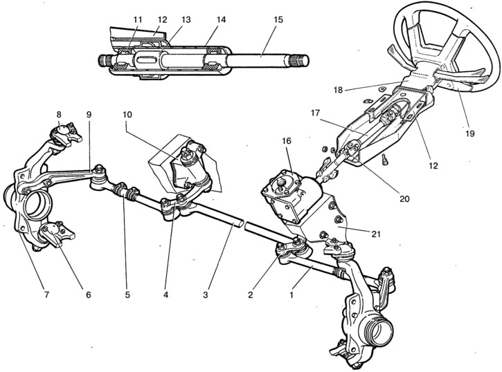
Pic. 5-1. Steering:
1 - lateral thrust; 2 - bipod; 3 - medium thrust; 4 - pendulum lever; 5 - adjusting clutch; 6 - lower ball joint of the suspension; 7 - right rotary fist; 8 - upper ball joint of the suspension; 9 - lever of the right steering knuckle; 10 - pendulum arm bracket; 11 - upper shaft bearing; 12 - steering shaft mounting bracket; 13 - lock sleeve; 14 - pipe bracket for mounting the steering shaft; 15 - upper steering shaft; 16 - steering gear housing; 17 - intermediate shaft; 18 - facing casing of the steering shaft; 19 - steering wheel; 20 - coupling bolt for fastening the cardan joint; 21 - body spar.
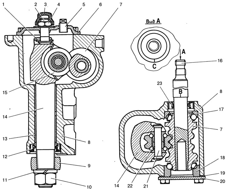
Pic. 5-2. Steering section:
1 - adjusting screw plate; 2 - adjusting screw of the bipod shaft; 3 - cap; 4 - screw nut; 5 - oil filler plug; 6 - cover; 7 - worm; 8 - crankcase; 9 - bipod; 10 - nut for fastening the bipod to the shaft; 11 - spring washer; 12 - stuffing box; 13 - bronze bushing; 14 - bipod shaft; 15 - bipod shaft roller; 16 - worm shaft; 17 - upper ball bearing; 18 - lower ball bearing; 19 - shims; 20 - lower cover of the worm bearing; 21 - roller axis; 22 - ball bearing; 23 - worm shaft seal; B, C - labels.
Since November 1998, a telescopic intermediate shaft has been installed on vehicles instead of a cylindrical intermediate shaft 17 (pic. 5-1) and the steering wheel 19 began to be fastened with a self-locking nut.
There are two options for installing the bipod shaft roller: on a needle or ball bearing. The text gives numerical data for both options, while under the sign «*» they refer to the first option - the bipod shaft roller is mounted on a needle bearing.