




- clamp base 4 (Fig. 2-33) of the device in a vice and install the connecting rod and piston group on it;
- lower the indicator bracket 8, insert the threaded rod 3 into the finger hole and push it into the hole in the boss until the head 2 of the rod rests against the end of the finger;
- screw nut 5 onto the end of the rod and tighten it so that it, in contact with the support, takes up any possible gaps;
- lift bracket 8 to a horizontal position, secure it with handle 7 and install pin 1 of indicator 9 on head 2 of the rod inserted into the finger;
- set the indicator to zero and insert stop 6 into the groove of the threaded rod so that the rod does not turn;
- using a torque wrench, apply a torque of 12.7 N·m (1.3 kgf·m) to nut 5 of the rod, corresponding to an axial load of 3.92 kN (400 kgf).
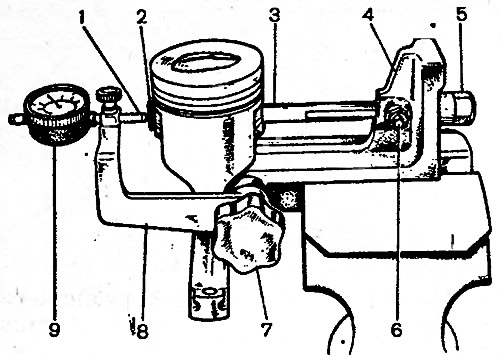
Fig. 2-33. Assembled piston-pin-connecting rod kit installed on fixture A.95615 for pin pressing-out test: 1 - indicator pin in contact with the end of the rod: 2 - arrow head in contact with the finger; 3 - threaded rod with groove; 4 - base; 5 - rod nut; 6 - rod stop pin, 7 - bracket clamp handle; 8 - indicator bracket; 9 - indicator
The pin is seated correctly in the connecting rod if, after the torque wrench is released and the nut is returned to its original position, the indicator arrow returns to zero.
If the pin slips in the upper head of the connecting rod, replace the connecting rod with a new one.