




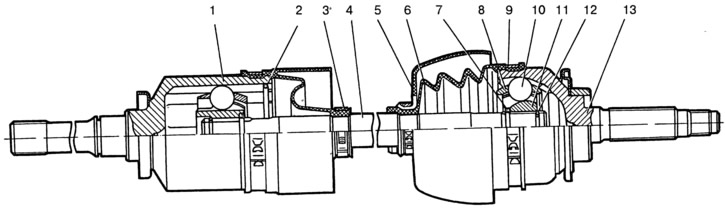
Fig. 3-82. Front wheel drive:
1 - inner hinge housing; 2 - retainer; 3 - cover mounting ring; 4 - wheel drive shaft; 5 - protective cover of the case; 6 - protective cover; 7 - thrust ring of the cage; 8 - separator; 9 - clamp; 10 - ball; 11 - outer hinge cage; 12 - retaining ring; 13 - outer hinge housing.
The joints are mounted on the ends of shaft 4. The outer joint is connected to the front wheel hub; it is of a rigid type, with angular freedom. The inner joint is of a universal type, with angular and axial freedom. It is connected to the half-axle gear of the front axle.
The outer hinge consists of a housing 13, a collar 11, a separator 8 with balls 10, a locking 12 and a thrust 7 ring. The collar 11 is connected to the housing 13 through balls that enter the grooves of the collar, made along the radius, and into the grooves of the housing. The collar is mounted on the splines of the shaft 4 until it stops in the ring 7 and is fixed by the locking ring 12. This ring in a compressed state freely passes through the splined opening of the collar 11, which allows the hinge and shaft 4 to be connected and disconnected.
The hinge is protected from dirt and moisture by cover 6, which, in turn, is protected from mechanical damage by casing 5. The protective cover is held on shaft 4 and on the hinge body by clamping clamps 9.
The internal hinge differs in its design from the external one in that it has straight grooves. The axial movement of the hinge parts in the housing is limited by a wire retainer 2.
The internal hinge parts and individual lots of the external hinge are sorted into several assembly groups by size, so during repairs it is not allowed to replace any one hinge part. It must be replaced as an assembly. Protective covers 5 and covers 6, clamps 9, ring 3 and retainer 2 can be replaced separately.