
Note. The engine cylinder head can be removed from the car as an assembly or, after partial disassembly, the camshafts can be removed. Both options are shown on the VAZ 21124 engine (1,6i). On the VAZ 2112 engine (1,6i) removal of the cylinder head is carried out in the same way (see text for features).
Removing
1. Drain the engine coolant (see items 1-7 "Coolant replacement").
2. Remove the rear timing belt cover (see "Rear timing belt cover - removal and installation").
3. Remove the head cover (see "Cylinder head cover - removal, installation, replacement").
Note. If the cylinder head is removed for its subsequent repair, it is better to partially disassemble it before removal:
A) remove camshafts (see "Camshafts - removal, installation, replacement");
b) remove the hydraulic lifters from the seats (see "Hydraulic compensators - removal, installation, replacement");
V) remove the fuel rail (see "Fuel rail engine 21124 (1,6i) - removal, installation, replacement");
G) remove the camshaft position sensor (see "Camshaft position sensor (DPRV) - removal, inspection, replacement");
d) disconnect from the engine bracket the upper rod of the power unit (see "Supports and rods of the power unit - removal and installation").
If disassembly of the cylinder head is not required (e.g. to replace the gasket), it should be removed assembled with camshafts, bearing housing, fuel rail, oil pressure and camshaft position sensors.
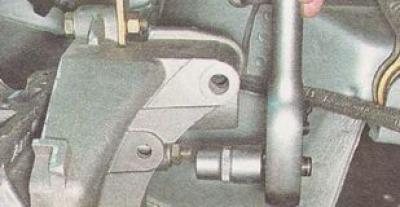
4. Disconnect the upper rod of the power unit from the bracket of the cylinder head (see "Supports and rods of the power unit - removal and installation").
5. Using a 13 mm socket wrench, unscrew the three nuts securing the rod bracket.
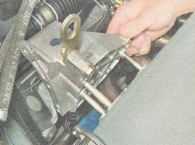
6. Remove the rod bracket from the studs.
7. On the engine 21124 (1,6i) remove catalytic manifold (see "Engine manifold catalyst VAZ 21124 (1,6i) - removal, installation, replacement").
On the engine 2112 (l,5i) remove exhaust manifold (see "Exhaust manifold of the VAZ 2112 engine (1,5i) - removal and installation") and inlet pipeline (see "The inlet pipeline of the VAZ 2112 engine (1,5i) - removal and installation").
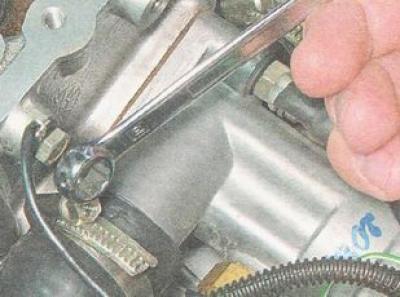
8. With a 10 mm wrench, unscrew the bolt securing the wire tip «masses» and disconnect it from the block head.
9. Using a 13 mm wrench, unscrew the nut securing the tip of the wire to the negative terminal of the battery and remove the tip from the stud.
10. In order not to damage the sensor connectors, disconnect the wires from the coolant temperature sensors of the engine management system (see "coolant temperature sensor (DTOZH) - removal and inspection") and temperature gauge (see point 3 "Coolant temperature gauge sensor - removal and inspection"), as well as from the camshaft position sensor, if we remove the cylinder head assembly (see point 2 "Camshaft position sensor (DPRV) - removal, inspection, replacement").
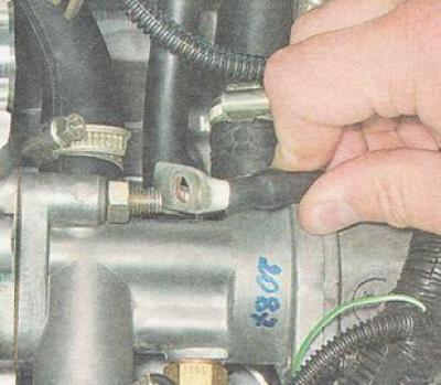
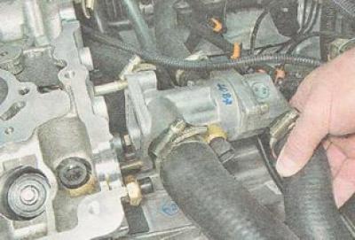
11. Using a 13 mm socket wrench, unscrew the two nuts securing the thermostat housing.
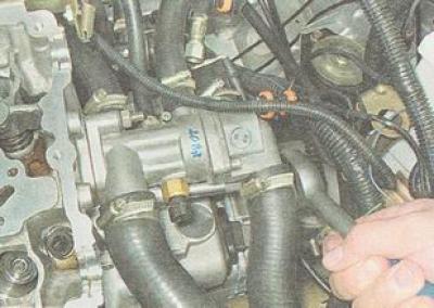
12. Removing the thermostat housing from the studs of the cylinder head and, without disconnecting the hoses, take it to the side.
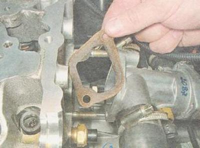
13. Remove the thermostat seal.
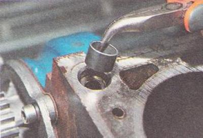
14. With a 10 mm hex wrench, unscrew ten bolts securing the head to the cylinder block in the specified sequence (see photo below).
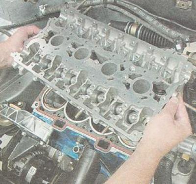
15. Remove the head from the cylinder block assembly...
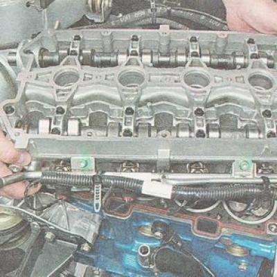
...or with the camshafts removed.
16. Remove the gasket:
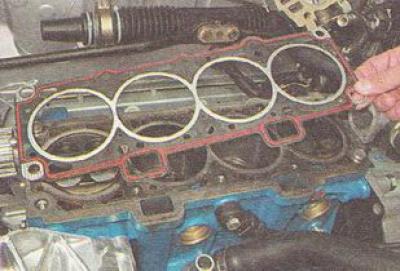
17. In order not to lose, we take out two guide bushings from the seats in the cylinder block.
Installation
1. We wash the cylinder head from dirt and deposits with kerosene or diesel fuel.
2. Remove from the threaded holes of the cylinder block (for head bolts) residual oil and coolant.
3. We clean the mating planes of the head and cylinder block from the remnants of the old gasket, degrease the planes with a solvent.
Warning. When installing a cylinder head on a vehicle, always use a new gasket. Oil must not be allowed to come into contact with the gasket surface.
4. We install the guide bushings of the cylinder head in the seats of the cylinder block. We lay the gasket on the cylinder block, while the guide bushings must enter the corresponding holes in the gasket.
5. Install the head on the cylinder block. Slightly moving the head from side to side, we ensure that the guide bushings enter the corresponding recesses of the cylinder head.
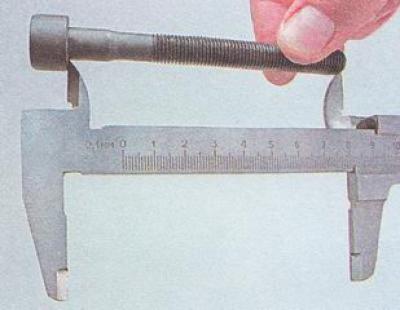
Warning. Reuse of the head bolts is allowed only if their length does not exceed 100 mm.
6. Using a caliper or a locksmith's ruler, we measure the length of the cylinder head bolts. Bolts longer than 100 mm are replaceable.
7. Before installation, we dip the threaded part of the bolts into engine oil, after which we let the oil drain, after waiting about half an hour.
8. We install the bolts of its fastening into the holes of the head. Using a torque wrench, tighten the cylinder head bolts in three stages - first with a torque of 20 Nm (2 kgf-m), then turn the bolts 90°and then turn the bolts 90°again. At the same time, we observe the sequence indicated in the photo (see below).
Further assembly of the engine is carried out in the reverse order.
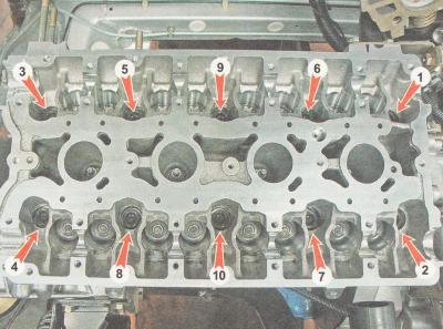
Cylinder head bolt loosening sequence
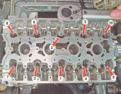
Cylinder head bolt tightening sequence.