
The air entering the engine cylinders is cleaned of dust by an air filter. Air filter mounted in the engine compartment on three rubber mounts. The filter element is replaceable, made of special paper. To prevent the ingress of polluted air into the intake tract, there is a sealing border at the top of the element. To replace the filter element, the filter cover is made removable. Purified air via mass air flow sensor (see more details. "Engine management system") passes through the air duct to the throttle valve.
throttle valve regulates the amount of air entering the engine cylinders. Pedal damper drive "gas" - cable. The damper rotates on an axis in the housing (branch pipe). The throttle body is studded to the intake module flange. The housing has a channel for the coolant. The channel is connected to the cooling system by rubber hoses. The circulation of coolant through the throttle body prevents freezing of the internal air cavities of the body in winter. Fittings are installed in the housing for connection with the adsorber and the engine crankcase ventilation system.
Throttle body with mounted throttle position sensor and idle air control (see more details. "Engine management system") form throttle assembly.
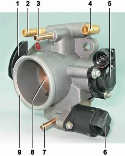
Throttle assembly: 1 - throttle actuator sector; 2, 4 - fittings for connection with the engine cooling system; 3 - crankcase exhaust fitting; 5 - throttle position sensor; 6 - idle speed regulator; 7 - fitting for connection with the adsorber; 8 - throttle valve; 9 - branch pipe of the throttle body
The fuel reserve is stored in a tank with a capacity of 43 liters. Fuel tank steel, welded from two stamped parts. The tank is suspended from the bottom of the car on two steel clamps. The filler neck of the fuel tank is displayed on the right side of the car and is closed with a stopper. Fuel from the tank is supplied by electric fuel pump submersible type.
The pump is installed in the fuel tank. To access the pump in the bottom of the car, under the rear seat cushions, a hatch with a cover is made.
A strainer is installed on the fuel pump inlet pipe to trap small solid particles of debris that have entered the fuel tank along with gasoline. The pump is energized by the ECU (see "Engine management system") when the ignition is turned on. If at the same time no attempt is made to start the engine, then after 2-3 seconds the ECU will turn off the fuel pump.
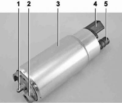
Fuel pump: 1 - ledge for attaching a strainer; 2 - fuel intake pipe for connecting a strainer; 3 - body; 4 - electrical connector block; 5 - day off (forcing) branch pipe for connection with the cover of the fuel module with a corrugated tube
Comment. On a car with an MP7.0 ECU, the first time you try to start the engine after connecting the battery, the fuel pump can only be turned on simultaneously with the starter. In the future, the fuel pump will work as on vehicles with other types of ECU. However, after three ignitions in a row without starting the engine, the fuel pump will only be turned on simultaneously with the starter
From the pump, through the corrugated tube of the fuel module, gasoline enters the fuel line and then to the fuel filter, where the fuel undergoes a more thorough cleaning.
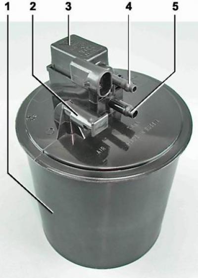
Fuel filter - paper, installed in a metal non-separable case.
The purified fuel enters the fuel rail through the fuel line.
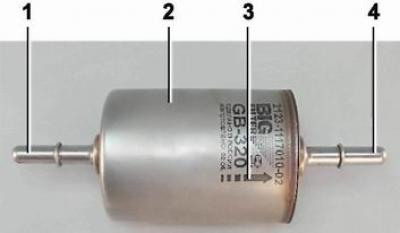
Fuel filter for engines 21124 and 21114: 1 - inlet pipe; 2 - body; 3 - fuel flow direction arrow (painted on the filter body); 4 - outlet pipe
Comment.The fuel filter of the 2112 and 2111 engines has threaded connectors.
fuel rail holds four nozzles and brings fuel to them. The connection of the ramp with the nozzles is sealed with rubber rings. The ramp is bolted to the cylinder head.
Fuel pressure control bypass valve that maintains in the system (in the fuel line) working pressure 284-325 kPa for engines 2112 and 2111 or 378-390 kPa for engines 21124 and 21114, necessary for the correct operation of the injection system (see more details. "Engine management system").
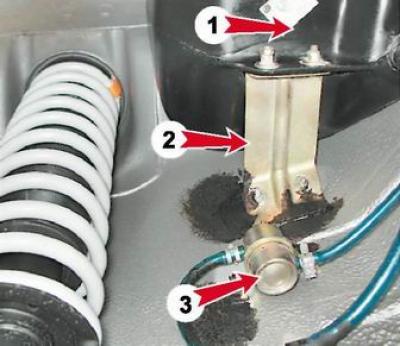
Separator location on vehicles with engines 21124 and 21114 (1,6i): 1 - separator; 2 - separator mounting bracket; 3 - gravity valve.
Note. On vehicles with engines 2112 and 2111, a safety valve is additionally installed here. On vehicles with engines 21124 and 21114, the safety valve is made in the filler cap.
In accordance with the environmental requirements of EURO II, the car is equipped with fuel vapor recovery system The overfuel space of the tank is connected with the atmosphere not directly, but through the elements of this system. The system consists of a separator, an adsorber, a gravity valve, an adsorber purge valve, a check valve, connecting pipes and hoses. The separator and gravity valve are fixed under the left rear fender of the car. Gasoline vapor is partially condensed in the separator and returned to the fuel tank. The gravity valve prevents fuel from escaping from the tank when the vehicle is overturned.
Adsorber: 1 - adsorber body; 2 - branch pipe for connecting the internal cavity of the adsorber with the atmosphere; 3 - adsorber purge valve; 4 - connecting branch pipe of the valve; 5 - adsorber connecting pipe
From the separator, uncondensed gasoline vapors through pipes and connecting hoses enter the adsorber, which prevents vapors from entering the atmosphere. An adsorber is a container where gasoline vapors are absorbed by activated carbon. When the engine is running at a high crankshaft speed, the ECU sends a signal to open the canister purge valve and gasoline vapors are sucked into the receiver.
Features of the power supply system of engines 2112 and 2111
Elements of the power supply system of engines 2112 and 2111 (1,5i): 1 - nozzles; 2 - fuel rail; 3 - diagnostic fitting; 4 - adsorber; 5 - check valve; 6 - throttle assembly; 7 - gravity valve; 8 - safety valve; 9 - separator; 10 - filler pipe of the fuel tank; 11 - fuel filter; 12 - fuel supply line; 13 - fuel line hose connecting the outlet (forcing) branch pipe of the fuel module with a fuel filter; 14 - fuel module; 15 - fuel tank; 16 - drain fuel line; 17 - fuel pressure regulator.
Note. The fuel supply line on the 2111 engine is connected to the fuel rail from the end (see below).
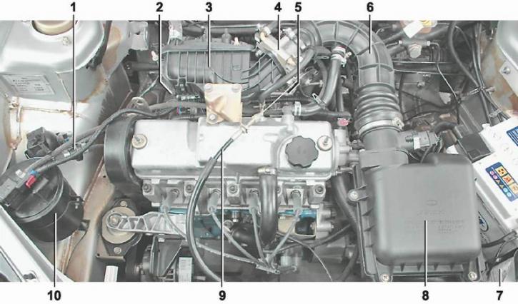
The location of the elements of the engine power system [Engine with trim removed.] 2112 (1,5i 16V) in the engine compartment: 1 - receiver; 2 - throttle assembly; 3 - air supply hose to the throttle valve; 4 - air filter; 5 - fuel pressure regulator; 6 - throttle cable; 7 - fuel rail; 8 - diagnostic fitting; 9 - adsorber check valve; 10 - adsorber
The location of the elements of the engine power system 2111 (1,5i 8V) in the engine compartment: 1 - adsorber check valve; 2 - diagnostic fitting; 3 - receiver; 4 - throttle assembly; 5 - fuel pressure regulator; 6 - air supply hose to the throttle valve; 7 - air intake; 8 - air filter; 9 - fuel rail; 10 - throttle cable; 11 - adsorber
Air is supplied to the intake valves of the cylinders of engines 2112 and 2111 through a receiver and an intake pipeline made of aluminum alloy.
Fuel pump combined with the fuel gauge sensor into a single unit - fuel module (often referred to as an electric fuel pump). The pressure pump delivers fuel from the tank through the fuel filter to the fuel rail.
Fuel pressure control installed on the fuel rail. Excess fuel is returned to the tank through the return line.
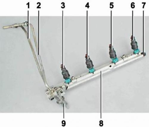
Fuel rail engine 2112 (1,5i 16V) complete With nozzles: 1 - fuel supply pipe to the fuel rail; 2 - fuel line tube for draining fuel into the tank; 3, 4, 5 and 6 - nozzles; 7 - diagnostic fitting (closed with screw cap for checking fuel pressure); 8 - fuel rail; 9 - fuel pressure regulator
Fuel rail engine 2111 (1,5i 8V) complete With nozzles: 1 - diagnostic fitting; 2 - fuel rail; 3 - tube for supplying fuel to the fuel rail; 4 - fuel pressure regulator; 5 - outlet tube (plum) fuel into the tank; 6, 7, 8 and 9 nozzles
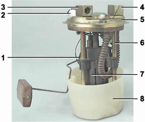
fuel engine module 2112 and 2111 (1,5i): 1 - fuel gauge sensor; 2 - connecting block; 3 - inlet pipe; 4 - day off (forcing) pipe branch; 5 - module cover; 6 - module cover guide; 7 - electric fuel pump in a plastic casing; 8 - intake chamber
Features of the power supply system of engines 21124 and 21114
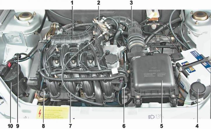
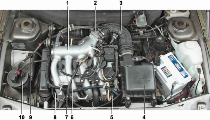
The location of the elements of the engine power system [Engine with trim removed.] 21124 (1,6i 16V) in the engine compartment: 1 - inlet pipeline; 2 - throttle assembly; 3 - air supply hose to the throttle valve; 4 - air intake; 5 - air filter; 6 - fuel rail; 7 - throttle cable; 8 - diagnostic fitting; 9 - adsorber check valve; 10 - adsorber
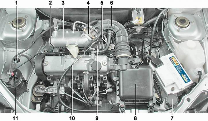
The location of the elements of the engine power system [Engine with trim removed.] 21114 (1,6i 8V) in the engine compartment: 1 - adsorber check valve; 2 - diagnostic fitting; 3 - receiver; 4 - throttle assembly; 5 - fuel rail; 6 - air supply hose to the throttle valve; 7 - corrugated air intake hose; 8 - air filter; 9 - throttle cable; 10 - adsorber
On the 21124 engine, the receiver is combined with the intake manifold into a single unit and is made of plastic. On the 21114 engine, only the receiver is made of plastic.
There are two valves in the fuel tank filler cap: one for emergency release of fuel vapor pressure from the tank (what happens when the ambient temperature rises), and the other - for the intake of air from the atmosphere when fuel is consumed from the tank (this eliminates the occurrence of a strong vacuum in the tank).
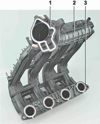
Engine intake manifold 21124 (1,6i 16V): 1 - a flange with a sealing ring for fastening a throttle branch pipe; 2 - receiver; 3 - intake manifold flange with sealing rings for connection to the cylinder head

Engine receiver 21114 (1,6i 8V): 1 - flange with a sealing ring for fastening the throttle pipe; 2 - receiver with sealing rings for connection to the inlet pipeline
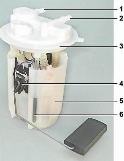
Fuel module for 21124 and 21114 engines (1,6i): 1 - inlet pipe (for supplying fuel to the pressure regulator); 2 - day off (forcing) pipe branch; 3 - module cover; 4 - fuel gauge sensor; 5 - intake chamber; 6 - module cover guide
The fuel pump is combined with the fuel level indicator sensor and the fuel pressure regulator into a single unit - the fuel module (often referred to as an electric fuel pump). Fuel from the pump (through the fuel module outlet) enters the fuel filter. The purified gasoline is again fed through the fuel line and through the tee to the inlet pipe of the fuel module and then fed into the fuel rail. Excess fuel flows through the pressure regulator back into the tank. The fuel pressure regulator is located in the fuel module cover.
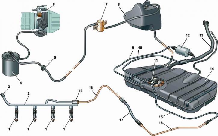
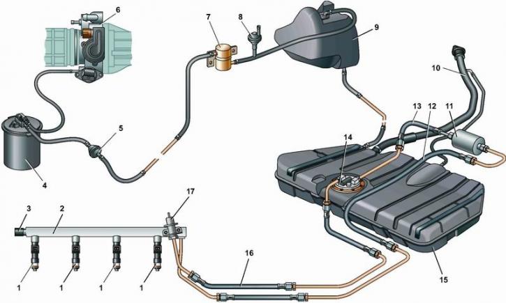
Scheme of the power supply system for engines 21124 and 21114 (1,6i): 1 - nozzles; 2 - fuel rail; 3 - diagnostic fitting; 4 - adsorber; 5 - check valve; 6 - throttle assembly; 7 - gravity valve; 8 - separator; 9 - fuel line tube connecting the fuel filter to the tee; 10 - fuel line tube connecting the fuel filter with the outlet pipe of the fuel module; 11 - fuel module; 12 - fuel filter; 13 - filling pipe; 14 - fuel tank; 15 - hose connecting the fuel filter and the fuel module with the fuel line; 16, 18 - metal tubes of the fuel line; 17 - connecting hose; 19 - fitting for connecting the fuel rail to the fuel line.
Note. On the 21114 engine, the shape of the fuel rail has minor differences (see below).
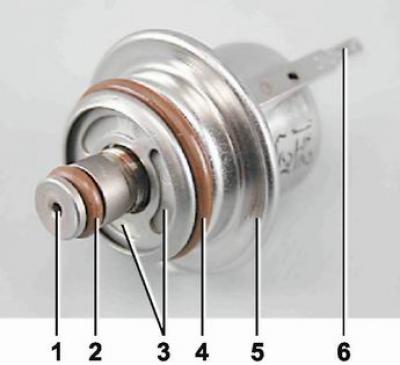
Fuel pressure regulator for engines 21124 and 21114 (1,6i): 1 - hole for dumping excess fuel; 2, 4 - sealing rings; 3 - holes for supplying fuel to the regulator; 5 - body; 6 - output for connecting the regulator with "weight"
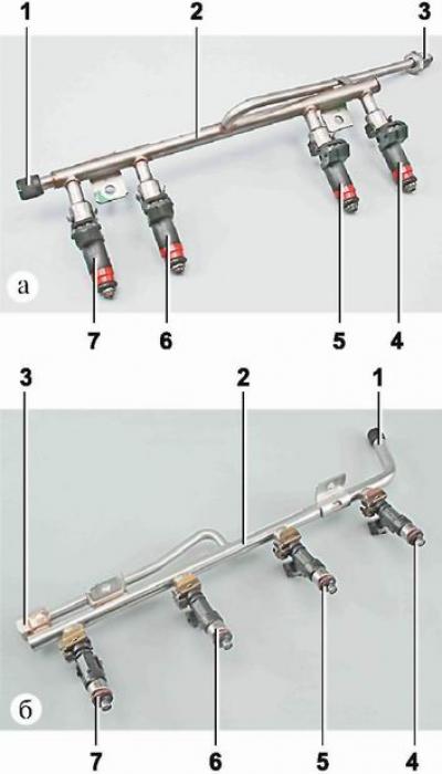
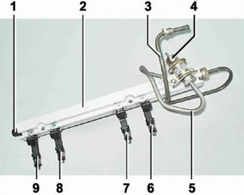
Fuel rail engines 21114 (1,6i 8V) (A) and 21124 (1,6i 16V) (b) complete with injectors: 1 - diagnostic fitting; 2 - fuel rail; 3 - fitting for connection with the fuel line; 4, 5, 6 and 7 - nozzles