
The fuel used is AI-93 gasoline.
The power supply system includes: fuel tank, fuel pump, air filter, carburetor, inlet and outlet pipelines, muffler pipe, main and additional mufflers.
Schematic diagram of the car engine power system «Niva» VAZ-2121 is shown in fig. 13. Fuel from tank 1 is supplied by pump 7 through pipelines to carburetor 4. Air enters carburetor through air filter 5. The combustible mixture prepared in the carburetor is supplied to the engine cylinders through the inlet pipeline 3. Exhaust gases are discharged from the engine cylinders into the atmosphere through the exhaust pipeline 2, pipe 8 mufflers and mufflers 9 and 10.
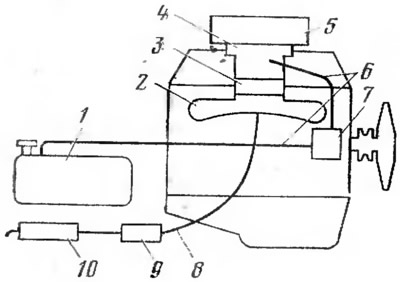
Pic. 13. Schematic diagram of the engine power system:
1 - fuel tank; 2 - exhaust pipeline; 3 - inlet pipeline; 4 - carburetor; 5 - air filter; 6 - pipelines; 7 - fuel pump; 8 - muffler pipe; 9 - additional muffler; 10 - main muffler.
Fuel tank The car has a capacity of 45 liters. A filled tank provides a car run of 350-400 km. The fuel tank is welded from two stamped steel trough-shaped halves. At the top of the tank has a filler neck with a sealed plug, and at the bottom - a drain hole with a plug. The amount of fuel in the tank is controlled by a gauge, the sensor of which is installed inside the tank. The connection of the tank with the atmosphere and its ventilation is carried out through an air tube.
Fuel pump (pic. 14) serves to supply fuel from the fuel tank to the carburetor. Diaphragm type fuel pump. Between the upper 3 and lower 13 parts of the pump housing there is a block of diaphragms 15, which is connected to the rod 7. The rod is covered by the forked end of the balancer 11 of the lever 12 of the pump drive. A spring 14 of the diaphragm block is installed on the rod. In the upper part of the pump housing there are suction 6 and discharge 16 valves. The pump is driven by a pusher from the eccentric of the oil pump drive shaft. Under the influence of the eccentric, the pusher presses the upper part of the lever 12, and the balancer 11 moves the diaphragm block 15 down through the rod 7. In this case, the spring 14 is compressed. The volume of the cavity above the diaphragm block increases, and under the action of vacuum from the tank, fuel enters the pump through the suction pipe 4, the strainer 2 and the suction valve 6. The pump discharge valve is closed. The diaphragm block moves upwards under the action of the spring 14, when the balancer 11 does not hold the rod 7. Under the pressure of the fuel, the discharge valve 16 opens, and the fuel enters the carburetor through the discharge pipe 1. The suction valve of the pump is closed in this case. When the float chamber of the carburetor is full, the float shut-off needle will block the flow of fuel into the carburetor. In this case, the diaphragm block of the fuel pump will remain in the lower position, and the lever 12 with the balancer will move idly. Lever 8 is used for manual pumping of fuel into the carburetor before starting the engine. It acts on the balancer 11 through the eccentric 10.
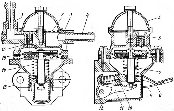
Pic. 14. Fuel pump:
1 - discharge pipe; 2 - mesh filter; 3 - the upper part of the body; 4 - suction pipe; 5 - cover; 6 - suction valve; 7 - stock; 8 - lever for manual fuel pumping; 9 - spring of the manual pumping lever; 10 - eccentric; 11 - balancer; 12 - mechanical fuel pumping lever; 13 - lower part of the body; 14 - spring of the diaphragm block; 15 - diaphragm block; 16 - discharge valve.
Air filter cleans the air entering the carburetor from dust and other impurities. The dust contains the smallest crystals of hard quartz, which, settling on the lubricated surfaces of parts, cause their intensive wear.
The air filter on a dry type car. It has a replaceable filter element consisting of a paper filter and a layer of synthetic wool. In the filter, the air during cleaning first passes through a layer of synthetic wool, and then through a paper filter element.
Carburetor prepares a combustible mixture corresponding to. composition of the engine operating mode. It is two-chamber, with a falling flow, balanced.
The carburetor has two mixing chambers, which are put into operation sequentially: first, the main (primary) chamber, and with an increase in load - an additional (secondary) camera. This made it possible to increase engine power due to better dosage and distribution of the combustible mixture over the engine cylinders. The flow of the combustible mixture in the chambers of the carburetor moves from top to bottom, which improves the filling of the cylinders with the mixture. Carburetor float chamber balanced (balanced), since its connection with the atmosphere is carried out through an air filter. This ensures that the carburetor prepares a combustible mixture that does not depend in its composition on the degree of clogging of the air filter.
Diagrams of carburetor systems and devices that provide the preparation of a combustible mixture under various engine operating modes are shown in fig. 15.
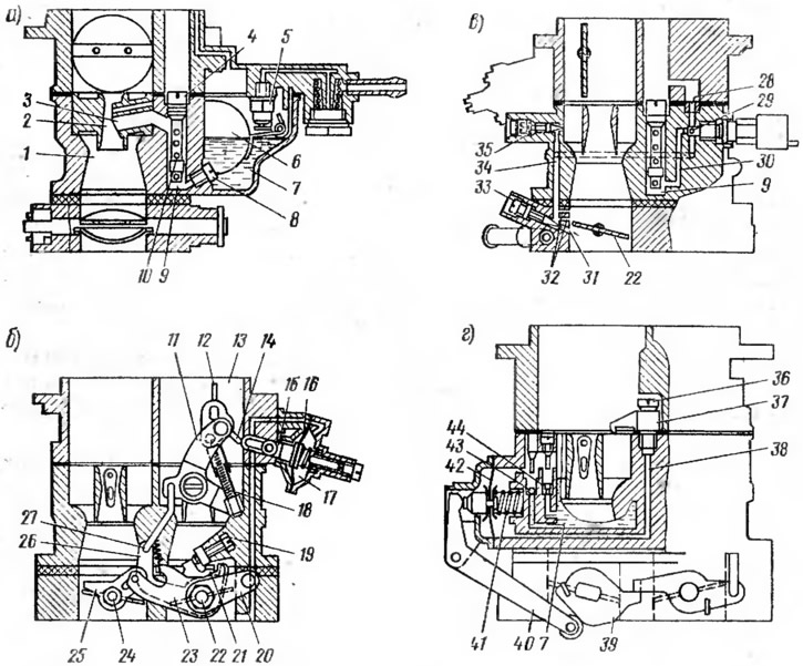
Pic. 15. Schemes of systems and devices of the carburetor:
a - main dosing system; b - starting device and throttle actuator; c - idle system; g - accelerator pump;
1 - large diffuser; 2 - small diffuser; 3, 47 - sprayers; 4, 28 - air jets; 5 - needle valve; 6 - float; 7 - float chamber; 8 - fuel jet; 9 - emulsion well; 10 - emulsion tube; 11 - air damper control lever; 12 - air damper; 13 - air pipe; 14 - draft air damper; 15 - stock; 16, 42 - diaphragms; 17 - rarefaction cavity; 18 - telescopic rod; 19 - throttle adjusting screw; 20 - throttle control lever; 21, 39 - sectors; 22 - throttle valve of the primary chamber; 23 - intermediate lever; 24 - throttle valve of the secondary chamber; 25, 26, 40 - levers; 27 - thrust; 29 - idle jet; 30, 38 - fuel channels; 31 - adjustable hole; 32 - openings of transient modes; 33, 35 - adjusting screws; 34 - emulsion channel; 36 - ball valve; 41 - diaphragm spring; 43 - inlet ball valve; 44 - bypass jet.
Main dosing system prepares a lean combustible mixture (1 kg of gasoline accounts for up to 16.5 kg of air) when the engine is running at partial (medium) loads. The composition of the prepared mixture is close to economical in the entire range of partial loads.
On fig. 15a shows the main dosing system of the primary chamber.
Fuel from the float chamber 7 of the carburetor through the main fuel jet 8 enters the emulsion well 9. In this well, the fuel is mixed with air leaving the holes of the emulsion tube 10, into which air enters through the air jet 4. The emulsion enters the small 2 through the atomizer 3 and large 1 carburetor diffusers and mixes with air passing through the diffusers, resulting in a combustible mixture. The main dosing system of the secondary chamber is designed and operates similarly to the primary one. The secondary throttle begins to open when the primary throttle is rotated about 50°from its original position.
Throttle actuator (pic. 15, b) is carried out through the lever 20 and sector 21, which are fixed on the axis of the damper 22 of the primary chamber of the carburetor. In this case, the lever 20 and sector 21 are rotated counterclockwise. The damper 22 opens, and the sector acts on the intermediate lever 23, which through the lever 25 opens the damper 24 of the secondary chamber of the carburetor. The full opening of the throttle valves of the primary and secondary chambers of the carburetor occurs simultaneously.
Starting device (see fig. 15, b) ensures the preparation of a rich combustible mixture (1 kg of gasoline contains less than 13 kg of air) when starting a cold engine. The starting device of the carburetor is the air damper 12, which is installed in the air pipe 13 of the primary chamber. When starting a cold engine, the three-arm lever 11, with the help of a rod 27 and lever 26, slightly opens the throttle valve 22 of the primary chamber of the carburetor. In this case, the telescopic rod 18 acts on the lever of the axis of the air damper 12, which closes the air pipe 13 in front of the atomizers and diffusers. The amount of air passing through the carburetor is reduced. The vacuum in the diffusers increases, and the fuel begins to flow out of the atomizers of the main dosing system of the carburetor, providing the formation of a combustible mixture. At the first flashes and subsequent engine idling, the vacuum from under the throttle valves is transferred to the cavity 17 under the diaphragm 16. The diaphragm bends and opens the air damper through the rod 15 and the rod 14 to access the required amount of air.
Idle system (pic. 15, in) prepares an enriched combustible mixture (1 kg of gasoline accounts for up to 13 kg of air) when the engine is idling. The fuel from the emulsion well 9 through the channel 30 enters the idle jet 29, where it mixes with the air entering through the air jet 28. The resulting emulsion is mixed with the air passing through the hole regulated by the screw 35. Then the emulsion exits under the throttle valve 22 of the primary chamber along channel 34 through hole 31, which is adjusted by screw 33. Holes 32, located above the throttle valve 22, ensure a smooth transition of the engine from idling to partial loads. Only the primary chamber of the carburetor is equipped with an idle system. The secondary chamber of the carburetor has a transition system that smoothly turns the chamber into operation at small throttle openings. According to the scheme and principle of operation, the transitional system of the secondary chamber is similar to the idle system of the primary chamber and is distinguished by the absence of adjusting screws.
accelerator pump (pic. 15, g) enriches the combustible mixture during a sharp transition of the engine from partial load to full (overtaking, etc.). It improves the throttle response of the engine, i.e., the ability to quickly develop maximum power.
With a sharp opening of the throttle valve of the primary chamber of the carburetor, sector 39, mounted on the damper axis, acts on lever 40, which presses on diaphragm 42. The diaphragm, overcoming the force of the return spring, bends and pushes fuel through channel 38, valve 36 and atomizer 37 into the primary diffuser cameras. Valve 43 is then closed. Sector 39 has a profile that provides dual fuel injection. Moreover, the second fuel injection coincides with the moment of opening the throttle valve of the secondary chamber of the carburetor.
Inlet and outlet pipelines. The inlet pipeline serves to uniformly supply the combustible mixture from the carburetor to the engine cylinders. It is cast from aluminum alloy. For better evaporation of the fuel deposited on the walls, the inlet pipeline has a heater (shirt), which is connected to the cooling jacket of the cylinder head.
The intake manifold heater is connected through a fitting to the carburetor throttle body heater. The connection of the inlet pipeline with the atmosphere is carried out using a special tube. The exhaust pipe carries the exhaust gases out of the engine cylinders. The pipeline is cast iron. The intake and exhaust pipes are attached to the cylinder head through a gasket.
Muffler reduces noise during the release of exhaust gases from the engine cylinders. The muffler of the car is steel, welded from two stamped halves. Inside the muffler there is a pipe with a large number of holes and transverse partitions. Outside, the muffler is covered with heat-insulating asbestos plates and enclosed in a protective steel casing. The exhaust gases entering the muffler expand and, passing through the holes in the pipe, sharply reduce their speed. This leads to a reduction in exhaust noise.