
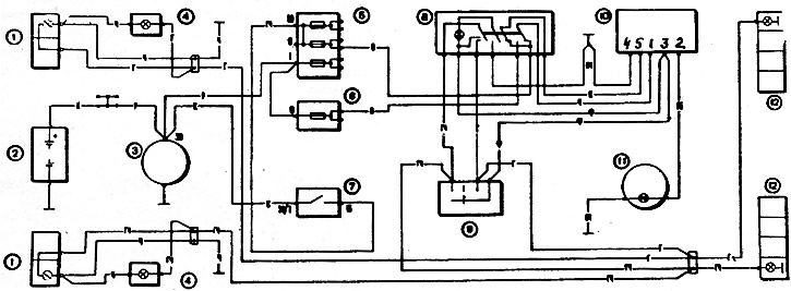
7-29. Scheme of the alarm system and direction indicators: 1 - front lights; 2 - battery; 3 - generator; 4 - side direction indicators: 5 - main fuse box; 6 - additional fuse box; 7 - ignition switch; 8 - alarm switch, 9 - switch of direction indicators, 10 - relay-interrupter of alarm and direction indicators; 11 - control lamp of direction indicators located in the speedometer; 12 - rear lights
The relay-breaker is mounted under the instrument panel on a bolt welded to the wall of the air intake box. A defective breaker relay cannot be repaired and must be replaced with a new one.
The relay-interrupter must ensure the blinking of the direction indicator lamps at a frequency of 90±30 cycles per minute at a rated load of 92 W, an ambient temperature of -20 to + 50°C and a voltage of 10.8 to 15 V.
Until 1985, a breaker type 23 3747 was used (pic. 7-30), assembled on integrated circuits Since 1985, a relay-breaker 231.2747 has been installed, made of discrete elements.
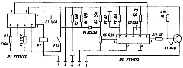
Pic. 7-30. Scheme of the relay-interrupter of alarms and direction indicators
The characteristics of both relay-breakers are the same. External difference is the absence of a plug «5» at the relay-breaker 231.3747. The supply voltage is only applied to the plug «7». Therefore, the brown wire connecting the plug is not needed «5» breaker relay with alarm switch. Relay-breaker 231.3747 creates a double flashing frequency of the control lamp 11 (see fig. 7-29) in the event of a burnout of any of the direction indicator lamps or an open in its power circuit.