
Attention! We measure and adjust clearances on a cold engine.
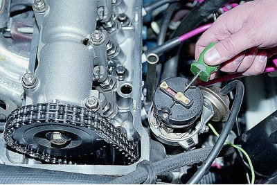
Removing the cylinder head cover (see Replacing the cylinder head cover gasket).
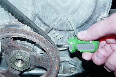
Remove the ignition switch cover (see Removal of a cover of the gauge distributor of ignition).
We turn the crankshaft by the nut securing its pulley clockwise..
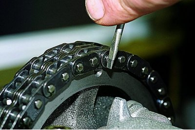
...until the label matches (drilling) on the camshaft sprocket with a protrusion on the bearing housing.
In this case, the mark on the crankshaft pulley should be located opposite the TDC mark (long) on the camshaft cover.
In this position of the shafts, corresponding to the end of the compression stroke in the 4th cylinder, we check and, if necessary, adjust the clearances at the exhaust valve of the 4th cylinder (8th cam) and inlet valve of the 3rd cylinder (6th cam).
Sequentially turning the engine crankshaft 180°clockwise, we check and adjust the clearances of the remaining valves in the order indicated in the table:
|
Angle of rotation of the crankshaft, hail. |
No. of adjustable valves (cams)
|
|
0
|
8 and 6
|
|
180
|
4 and 7
|
|
360
|
1 and 3
|
|
540
|
5 and 2
|
The angle of rotation of the crankshaft can also be controlled by the distributor slider. When the crankshaft is rotated 180°, the slider will rotate 90°.
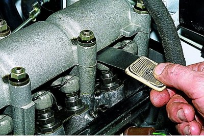
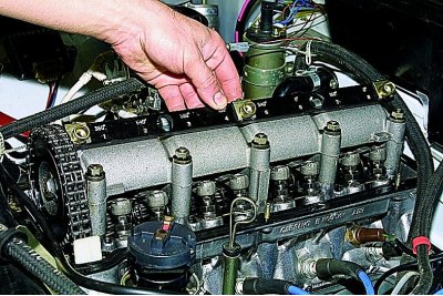
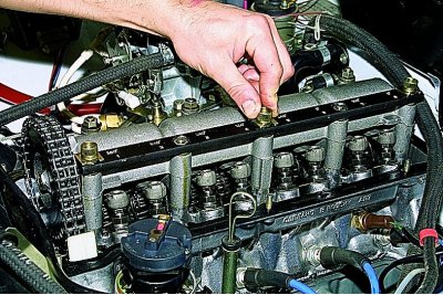
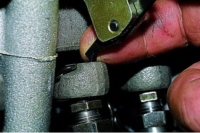
To check the clearance, we insert a wide flat feeler gauge 0.15 mm thick between the valve lever and the camshaft cam for the intake valve or 0.20 mm for the exhaust valve.
With a normal gap, the probe should enter with a slight bite.
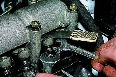
To adjust the gap with a wrench «at 17» loosen the locknut of the adjusting bolt, and with a wrench «at 13» turn the adjusting bolt, setting the required clearance.
Tighten the locknut while holding the adjusting bolt from turning. Again, check the gap and, if necessary, repeat the adjustment.
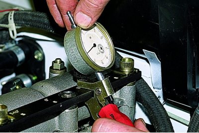
You can adjust the clearance in the valve mechanism using a tool with an indicator. For this…
... install the fixture bar on the camshaft bearing housing..
... and fix the bar on the body mounting studs.
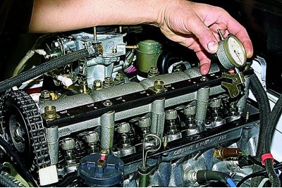
We install the rack with the indicator on the fixture bar opposite the valve to be checked,...
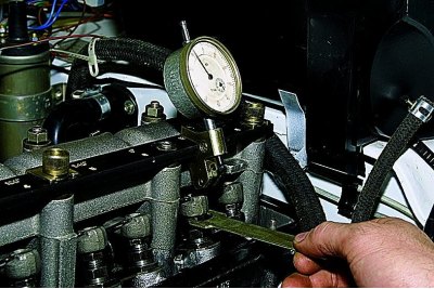
... supporting the ledge of the rocker of the indicator stand on the back of the head of the valve lever.
We fix the indicator stand on the bar. Having rested the indicator leg on another ledge of the rack rocker,..
... we fix the indicator on the rack.
Raising the valve lever with the fork plate of the device, we determine the gap in the valve mechanism by the indicator in accordance with the instructions for the device.
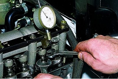
If necessary, adjust the gap.