




Insert liners without a groove on the inner surface into the middle main bearing socket and into its cover, and insert liners with a groove into the remaining sockets and corresponding covers1. The crankshaft is placed in the main bearings and two thrust half rings are inserted into the rear support sockets with the recesses facing the thrust surfaces of the crankshaft, with a steel-aluminum half ring being placed on the front side of the rear support and a metal-ceramic half ring on the rear side (yellow color). For engines produced before 1980, it is also necessary to install a metal-ceramic half ring.
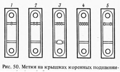
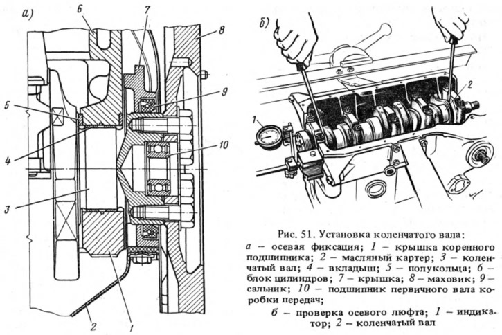
Install the main bearing caps in accordance with the marks (Fig. 50). Then check the axial clearance of the crankshaft (clearance between thrust half rings and thrust surfaces of crankshaft). To do this, install indicator 1, as shown in Fig. 51, b, and move the shaft with screwdrivers, checking the axial clearance using the indicator, which should be within 0.06-0.26 mm. If the gap exceeds 0.26 mm, the thrust half rings 5 are replaced with new ones or repair ones, increased by 0.127 mm.
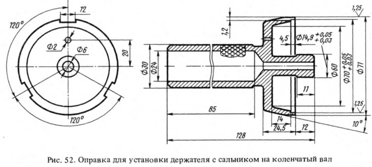
Place the rear oil seal holder gasket on the crankshaft flange and insert the bolts for fastening the front clutch housing cover into the holder sockets. Place the holder with the oil seal on the mandrel 41.7853.4011 (Fig. 52) and, having moved it from the mandrel to the crankshaft flange, attach it to the cylinder block. Install the front cover 6 (see fig. 48) clutch housing.
Install the flywheel on the crankshaft so that the mark B (cone-shaped hole) near the rim (see fig. 11) was located opposite the axis of the crank pin of the 4th cylinder. After this, the flywheel is locked with the A.60330/R lock (see fig. 48) and are attached to the crankshaft flange.
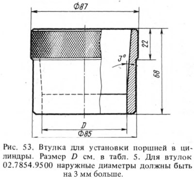
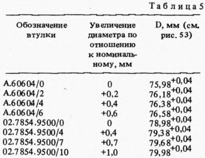
Using a bushing (Fig. 53) from set A.60604 for 2101 engines or 02.7854.9500 for 21011 engines, insert the pistons with connecting rods into the cylinders. The "P" mark on the pistons should be facing the front of the engine. The bushing sets (Table 5) for crimping piston rings during installation of pistons in cylinders include four bushings - one for pistons of the nominal size and three for increased (repair) portion size. Therefore, it is necessary to select a bushing suitable for the given size of the piston being installed.
Install the liners in the connecting rods and connecting rod caps, connect the connecting rods to the crankshaft journals and tighten the connecting rod bolts. The caps are installed so that the cylinder number on the cap is opposite the cylinder number on the lower connecting rod head.
Place the sprocket and oil pump drive shaft on the crankshaft and secure it with a thrust flange.
The cylinder head with the gasket is installed on the two centering bushings on the block and the mounting bolts are tightened in 2 steps, as indicated in Section. "Cylinder head and valve mechanism".
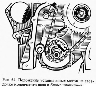
Turn the flywheel so that the mark on the crankshaft sprocket coincides with the mark on the cylinder block (Fig. 54). Put on (preliminary) sprocket on the camshaft assembled with the bearing housing and turn it so that the mark A (see fig. 56) on the sprocket was opposite mark B on the bearing housing, then remove the sprocket and, without disturbing the position of the shaft, install the bearing housing on the cylinder head and secure it by tightening the nuts in a certain sequence (see fig. 12). After this, the chain guide is installed on the cylinder head.
Install the camshaft drive chain in the following sequence:
- lubricate the chain with engine oil, place it on the camshaft sprocket and insert it from above into the drive cavity, installing the sprocket so that the mark on it coincides with the mark on the bearing housing (see fig. 56). Then install the lock washer and the sprocket mounting bolt, without tightening it all the way;
- the sprocket, lock washer and bolt are installed on the oil pump drive shaft without tightening it completely;
- place the chain on the crankshaft sprocket and install the chain tensioner shoe and tensioner without tightening the cap nut so that the tensioner spring can press the shoe; the chain limiting pin is screwed into the cylinder block;
- turn the crankshaft two revolutions in the direction of rotation, which will provide the necessary chain tension, and check that the marks on the sprockets match the marks on the cylinder block (see fig. 54) and on the bearing housing (see fig. 56). If the marks match, then, having locked the flywheel with the A.60330/R lock, finally tighten the sprocket bolts, the cap nut of the chain tensioner and bend back the lock washers of the sprocket bolts. If the marks do not match, then repeat the operation for installing the sprocket.
(The information is published on the website VazBook)
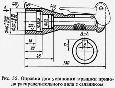
Adjust the clearance between the camshaft cams and the valve drive levers. Install the camshaft drive cover with the gasket and seal on the cylinder block without finally tightening the mounting bolts and nuts. Use mandrel 41.7853.4010 (Fig. 55) to center the cover relative to the end of the crankshaft and finally tighten the nuts and bolts for its mounting. Install the crankshaft pulley and tighten the ratchet.
Lubricate the oil filter ring with oil and install the filter, screwing it manually to the nipple on the cylinder block. Install the crankcase ventilation oil separator, the breather cover and secure the oil separator drain pipe retainer. Install the oil pump and oil sump with a gasket.
Install the coolant pump, generator bracket and generator. Put the belt on the pulleys and adjust its tension. Install the heater radiator feed pipe and outlet pipe on the cylinder head. Attach the heater radiator outlet pipe to the coolant pump and outlet manifold. Install the control instrument sensors, oil pump drive gear and ignition distributor.
An ignition distributor is installed for the following reasons:
- remove the cover from the ignition distributor, check and, if necessary, adjust the gap between the breaker contacts;
- turn the crankshaft until the start of the compression stroke in the 1st cylinder, and then, continuing to turn the crankshaft, align mark 4 with mark 2 (see fig. 57);
- turn the rotor to a position in which its outer contact is directed towards the contact of the 1st cylinder on the distributor cap and, holding the distributor shaft from turning, insert it into the socket on the cylinder block so that the center line passing through the spring latches is approximately parallel to the center line of the engine.
The distributor is secured to the cylinder block, the cover is installed and the wires are connected.
Screw the spark plugs into the cylinder head using key 67.7812.9515 and tighten with a torque handle.
The fuel pump is installed in accordance with the instructions in Section 1.9 "Power supply system". Install the heat-insulating shield with gaskets, the carburetor and connect the hoses to it. Close the carburetor with a technological plug. Install the cylinder head cover with a gasket and a fuel line bracket. Pour oil into the neck on the cylinder head cover.
Notes
1. Since 1987, all lower main bearing shells have been used without grooves on the inner surface.