
Disassembly and inspection
Before checking the connecting rod and piston group, the rings are removed from the piston and cleaned of carbon deposits, deposits are removed from the lubrication channels of the piston and connecting rod. Then check if there are any damages on the parts. Cracks of any nature on the piston, piston rings, pin, connecting rod and its cover are unacceptable. In this case, replacement parts are required.
To replace the piston, piston pin or connecting rod, they are disassembled, for which the finger is pressed out under pressure (with a force of at least 800 kgf) using mandrel A.60308, centered in the hole of the piston pin, and a support with a cylindrical recess in which the piston fits. Mandrel A.60308 is a stepped rod with a diameter and length of the working part, respectively, 21 and 80 mm. Centering shank diameter (14,9±0,05) mm. The use of a hammer for pressing and pressing is unacceptable, as the piston may be damaged.
Before assembly, check the gaps of the mates, which must correspond to the data tab. 2.
The fit of the piston pin to the piston is checked by inserting a selected piston pin, previously lubricated with engine oil, into the bore of the piston boss. The landing is considered normal if the piston pin enters the hole with a simple thumb pressure and does not fall out of the boss when the piston is held vertically with the piston pin. If the finger falls out of the boss, then it is replaced with a finger of the next category. If there was a category 3 finger in the piston, then in this case the piston with the finger is replaced.
The height gaps between the rings and grooves are checked with a set of feelers, placing the ring in the corresponding groove.
In the lock of the rings, the gap is checked by inserting them into a gauge having a hole diameter equal to the nominal diameter of the ring with a tolerance of±0.003 mm. For this purpose, you can use the caliber A.96137 (for engines 2101) or 67.8125.9501 (for engines 21011)1.
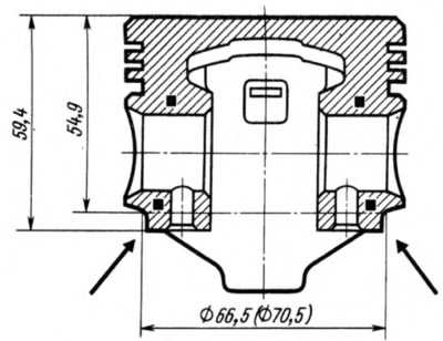
When replacing pistons, it is necessary to select them by weight, since the pistons of one engine should not differ by more than 2.5 g. sides on the lower outer side of the piston pin bosses (pic. 6). Metal removal, however, must not exceed 4.5 mm in height relative to the nominal piston height (59.4 mm), and the width is limited to a diameter of 66.5 mm (70.5 mm for engine model 21011).
Assembly
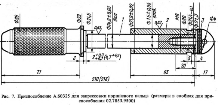
The pin is pressed into the upper head of the connecting rod with an interference fit, therefore, to facilitate this operation, the connecting rod is heated by keeping it in an oven at 240°C for at least 15 minutes. The pin should be pressed in as soon as possible, since the connecting rod cools quickly, and in a cooled connecting rod it is impossible to change the position of the pin. The latter must be prepared in advance for assembly by putting it on roller 1 (pic. 7) fixture A.60325 and installing guide 2 at the end of this roller, fixed with screw 3. The screw is loosely tightened so that jamming does not occur when the finger expands from contact with the heated connecting rod. When pressing the piston pins into the pistons of engines 21011, it is necessary to use tool 02.7853.9500 instead of A.60325.
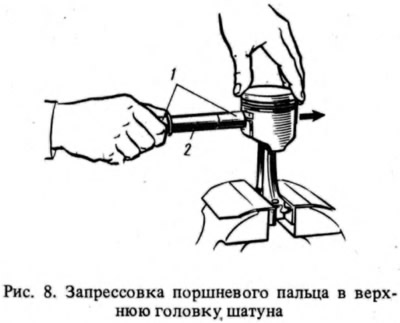
The connecting rod removed from the furnace is quickly clamped in a vice and the piston is put on the connecting rod so that the mark "P" on the piston was on the output side of the oil hole on the lower head of the connecting rod. Push the piston pin 2 fixed on the fixture 1 into the piston bore and the upper head of the connecting rod (pic. 8) until it stops the edge of the handle of the device in the piston. During this operation, the piston must be pressed against the upper head of the connecting rod in the direction of pressing the pin, as shown by the arrow. Thus, the finger will take the correct position. After cooling the connecting rod, lubricate the finger with engine oil through the holes in the piston bosses.
After assembling the piston with the connecting rod, the strength of the pin is checked using tool A.95615 (fig.9). To do this, clamp the base 4 of the fixture in a vise, lower the indicator bracket 8 and install a piston with a connecting rod on the fixture. Threaded rod 3 is inserted into the hole of the finger and advanced until the head 2 of the rod stops against the end of the finger. Nut 5 is screwed onto the end of the rod and tightened so that it, in contact with the support, selects possible gaps. Raise the bracket 8 to a horizontal position, fix it with the handle 7 and install the pin 1 of the indicator 9 on the head 2 of the rod inserted into the finger. Set the indicator needle to zero and insert stop 6 into the groove of the threaded rod so that the rod does not turn. Nut 5 is tightened with a torque wrench with a torque of 1.3 kgf·m, corresponding to an axial load of 400 kgf.
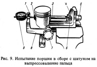
The landing of the pin in the connecting rod will be correct if, after the termination of the torque wrench and the return of the nut to its original position, the indicator needle returns to zero. If the pin slips in the upper head of the connecting rod, the connecting rod must be replaced with a new one.
After checking the pressing of the finger, lubricate the grooves on the piston and piston rings with engine oil. Install the rings on the piston, orienting them so that the lock of the upper compression ring is located at an angle of approximately 45°to the axis of the piston pin, the lock of the lower compression ring is at an angle of approximately 180°to the axis of the lock of the upper compression ring, and the oil scraper ring lock is at an angle of approximately 90°to the lock axis of the upper compression ring.
The lower compression ring is installed downwards with a groove that it has on the outer surface. If the ring is marked ''Top" or "TOR", then the ring is installed with the mark up. For oil scraper rings manufactured before 1987, the chamfers on the outer surface were asymmetrical. Therefore, these rings must be installed on the piston with chamfers up. Before installing oil scraper rings, it is checked that the joint of the spring expander is located on the side opposite to the ring lock.
Notes
1. Caliber A.96137 - a ring 26 mm thick with an outer diameter of 122 mm and an inner (76±0,003) mm. Caliber 67.8125.9501 differs from A.96137 only in the inner diameter.