




Remove protective caps 2 (Fig. 6-19), then press pistons 4 together with the parts of the automatic clearance adjustment device between the brake shoes and the drum out of cylinder body 3.
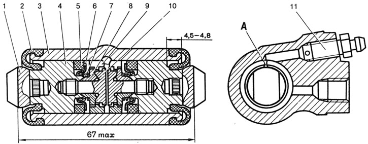
Fig. 6-19. Wheel cylinder:
1 - brake shoe stop; 2 - protective cap; 3 - cylinder body; 4 - piston; 5 - seal; 6 - support cup; 7 - spring; 8 - crackers; 9 - thrust ring; 10 - stop screw; 11 - nipple; A - slot on the thrust ring.
Install the piston assembly with the automatic device on a special fixture so that the fixture projections cover the head of the stop screw 3 (Fig. 6-20). Using a screwdriver, turn the piston 9 and unscrew the stop screw 3 from the piston. Remove the seal 8 with the support cup 7 and crackers 5 from the screw. Disconnect the stop ring 4 and the stop screw 3.
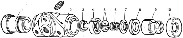
Fig. 6-20. Wheel cylinder parts:
1 - piston assembly; 2 - cylinder body; 3 - stop screw; 4 - thrust ring; 5 - crackers; 6 - spring; 7 - support cup; 8 - seal; 9 - piston; 10 - protective cap.
Assemble the automatic device and the wheel cylinder itself in the reverse order, taking into account the following:
- tighten the piston stop screws with a torque of 4-7 N·m (0.4-0.7 kgf·m);
- slot A (Fig. 6-19) on the thrust rings must be directed vertically upwards; deviation from the vertical is allowed no more than 30°. This location of the slot ensures more complete removal of air from the brake mechanism drive during its bleeding;
- to pre-compress the thrust rings, press the pistons into the cylinder body using a special device shaped like a cylinder with a conical inner hole;
- the force required to press the piston into the cylinder must be at least 350 N (35 kgf); if the force is less than 350 N (35 kgf), replace the thrust ring;
- when pressing the piston into the cylinder, it is necessary to maintain dimensions of 4.5-4.8 mm and 67 mm (maximum) (Fig. 6-19) for a free fit of the brake drum;
- before installing the parts into the cylinder body, lubricate them generously with brake fluid.
After assembly, check the movement of each piston in the cylinder body. They should move easily within 1.25-1.65 mm. Lastly, install the protective caps 2.