
Removal and installation
Disconnect lever 12 (pic. 6-22) from the rod 7, and then the clip 18 from the bracket 14 and the bracket for fastening the pipelines going to the pressure regulator.
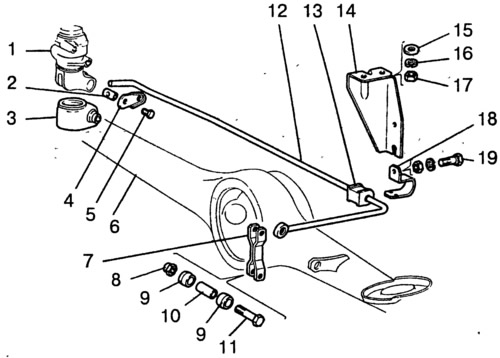
Pic. 6-22. Pressure Regulator Actuator Details:
1 - pressure regulator; 2 - axis of the regulator drive lever; 3 - dirt cap; 4 - locking plate; 5 - bolt with spring washer; 6 - rear axle beam; 7 - rod connecting the pressure regulator drive lever with the rear axle bracket; 8 - washer of bolt 11; 9 - plastic sleeve; 10 - spacer sleeve; 11 - a bolt of fastening of draft; 12 - pressure regulator drive lever; 13 - support bushing of the drive lever; 14 - support sleeve bracket; 15 - washer; 16 - spring washer; 17 - nut; 18 - holder of the support sleeve; 19 - a bolt of fastening of a clip to an arm.
Disconnect the muffler suspension parts from the body and take the pipeline with the mufflers to the side.
Having unscrewed the bolts securing the regulator to the bracket and the bracket to the body, remove the regulator bracket, and then, lowering the regulator down, disconnect the pipelines from it.
Remove the regulator and disconnect the drive lever from it. Plug the inlets and outlets of the pressure regulator and piping.
Install the pressure regulator in the reverse order of removal. Before tightening the regulator mounting bolts, install tool 67.7820.9519 on the end of the regulator drive lever (rice. 6-6). Direct the tool rod up until it stops in the body. This sets the distance (150±5) mm (see «Adjusting the position of the pressure regulator») between the end of the lever 2 and the side member of the body.
Lift up the protective cap 3 (pic. 6-22) and, turning the regulator on the fastening bolts, ensure that the end of the lever is in light contact with the regulator piston.
While holding the regulator in this position, tighten the bolts of its fastening to failure, then coat the axle 2 and the protruding part of the piston with a layer of grease DT-1 or Ditor. Reinstall the rubber cap 3, filling it with 5-6 g of the same lubricant.
Remove fixture 67.7820.9519 and connect the end of the lever with the rod 7, having previously coated with grease DT-1 or Ditor the bushings of the hinged connection of the rod with the lever.
Attach the pipes of the exhaust system to the body.
Bleed the brakes to remove air from the rear brake actuator.
Disassembly and assembly
Using the key A.56124, unscrew the plug, remove the gasket 5 (pic. 6-23), remove piston 10, spacer sleeve 2, seal 7, disc 8, spring 9 and thrust washer with sealing ring 3.
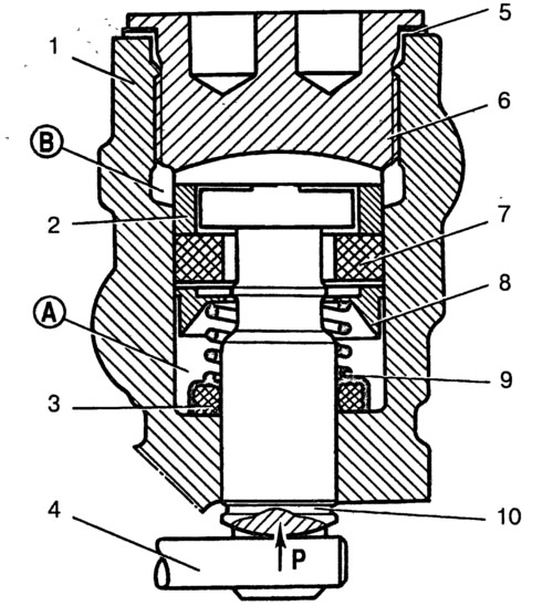
Pic. 6-23. Rear brake pressure regulator in non-working position:
A - normal pressure cavity; B - adjustable pressure cavity; P is the force transmitted by the lever 4 of the regulator drive; 1 - regulator housing; 2 - spacer sleeve; 3 - sealing ring; 4 - regulator drive lever; 5 - gasket; 6 - cork; 7 - sealant; 8 - spring plate; 9 - piston spring; 10 - piston.
When assembling, which is carried out in reverse order, lubricate all parts with brake fluid.
Warning: To distinguish the pressure regulator of VAZ-2121 and 21213 cars from the pressure regulators of other cars similar in appearance, there is a groove on the bottom of the piston.
Wash parts with isopropyl alcohol or brake fluid and inspect. The surfaces of the parts should not have scratches and roughness.
Check the condition and elasticity of the spring, the length of which in the free state should be 17.8 mm, and under load 76.44-64.68 N (7.8-6.6 kgf) - 9 mm.
Replace damaged parts, as well as the seal and the sealing ring.