
The main dimensions of the camshaft and bores in the camshaft bearing housing
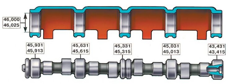
Camshaft - cast iron, cast, rotates on five bearings in a cast aluminum bearing housing mounted on the cylinder head. It is kept from axial movements by a thrust flange placed in the groove of the front bearing journal of the shaft. The main dimensions of the camshaft and camshaft bearing housing are given in the figure.
On VAZ vehicles until April 1982, camshafts with cams and bearing journals hardened by high-frequency currents were installed. From April 1982, nitrided camshafts were installed. Since 1984, the year of manufacture has been marked on the shafts. Since 1985, camshafts with cam cams have been installed; these shafts have a distinctive hex collar between the 3rd and 4th jaws.
Cylinder head section by exhaust valve
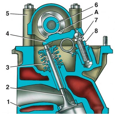
1 – a head of cylinders; 2 - exhaust valve; 3 - oil deflector cap; 4 – valve lever; 5 – the case of bearings of a camshaft; 6 - camshaft; 7 - adjusting bolt; 8 - bolt locknut; A - the gap between the lever and the camshaft cam
The valves are actuated by the camshaft through short steel levers 4. The levers swing on the spherical head of the bolt 7, which regulates the gap A between the camshaft cams and the levers.
Camshaft Drive Diagram
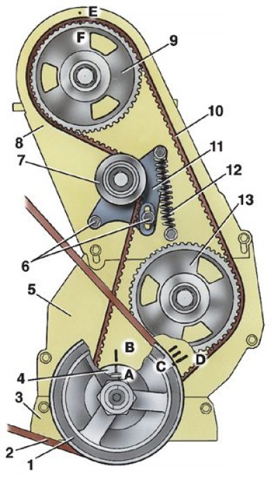
1 - crankshaft pulley; 2 - fan drive belt; 3 - bottom protective cover; 4 – a gear pulley of a cranked shaft; 5 – middle protective cover; 6 - bolts for fastening the tension roller bracket; 7 - tension roller; 8 – top protective cover; 9 - camshaft pulley; 10 - toothed belt; 11 - tension roller bracket; 12 – bracket spring; 13 – a pulley of a roller of a drive of the oil pump; And – a label on a gear pulley of a cranked shaft; B, D - TDC marks on the camshaft drive cover; C - mark on the crankshaft pulley; E - a label on a cover of a head of cylinders; F - mark on the camshaft pulley
The camshaft is driven from the drive pulley 4 of the crankshaft by a toothed belt. The same belt drives the pulley 13 of the oil pump drive shaft. The belt tension is adjusted using the tension roller 7, which is mounted on the bracket 11 and rotates on a double-row ball bearing.
The drive is isolated from oil by three oil seals covering the pulley hubs. Outside, the drive is closed with three plastic covers: top, middle and bottom (see fig. Dismantling the front of the engine).