




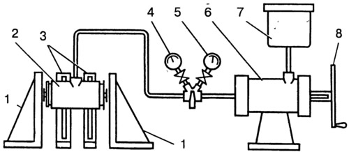
Fig. 6-21. Rear brake wheel cylinder test diagram:
1 - piston stops; 2 - test cylinder; 3 - cylinder bracket; 4 - low pressure gauge; 5 - high pressure gauge; 6 - cylinder for creating pressure; 7 - vessel; 8 - flywheel.
Adjust stops 1 so that the wheel cylinder pistons rest against them.
Check for fluid leaks. Connect low pressure gauge 4. Slowly rotating flywheel 8, set the fluid pressure to 0.05 MPa on gauge 4 (0.5 kgf/cm²).
Make sure that the set pressure is maintained for 5 min. Repeat a similar test at a liquid pressure of 0.1-0.2-0.3-0.4-0.5 MPa (1-2-3-4-5 kgf/cm²).
Reduce the pressure and connect the high pressure gauge 5. Make sure the pressure is maintained for 5 min, repeat the test at a liquid pressure of 5-10-15 MPa (50-100-150 kgf/cm²).
Pressure loss due to fluid leakage through sealing elements, pipe connections, bleed nipples or through casting pores is not permitted.
A slight decrease in pressure is allowed (no more than 0.5 MPa (5 kgf / cm²) for 5 minutes, especially at higher pressures, due to shrinkage of the seals.
The information is published on the website vazbook.ru