
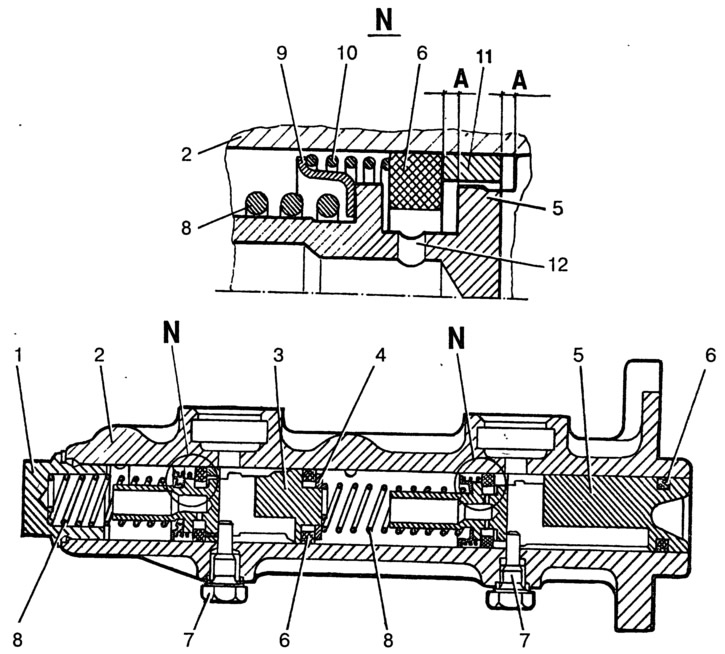
Pic. 6-9. Master cylinder:
1 - cork; 2 - cylinder body; 3 - front brake drive piston; 4 - washer; 5 - piston of the rear brake drive and additional drive of the front brakes; 6 - sealing ring; 7 - locking screws; 8 - piston return springs; 9 - spring plate; 10 - clamping spring of the seal; 11 - spacer ring; 12 - inlet; A - compensation hole (gaps between seal 6, ring 11 and piston 5).
Removal and installation
Disconnect the flexible hoses from the master cylinder and cover the hoses and fittings on the cylinder to prevent leakage of fluid from the reservoir and entry of dust, dirt or foreign matter into the cylinder.
Disconnect the steel pipelines from the master cylinder that drain fluid to the wheel cylinders of the front and rear brakes by first unscrewing the tube nuts.
Remove the cylinder by unscrewing the nuts securing it to the vacuum booster.
Install the smooth cylinder in the reverse order of removal. After installing the cylinder, bleed the hydraulic drive system to remove air from it.
Disassembly and assembly
Remove fittings 2 (pic. 6-10) with connecting sleeves 3, unscrew the locking bolts 5 and take out all the parts in the order shown in fig. 6-10.
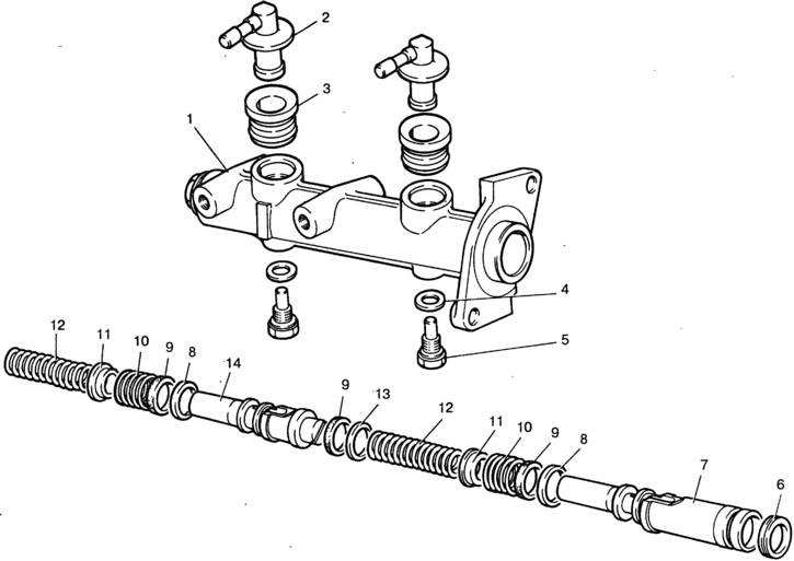
Pic. 6-10. Master Cylinder Details:
1 - cylinder body; 2 - fitting; 3 - connecting sleeve; 4 - sealing washer; 5 - locking bolt; 6, 9 - sealing rings; 7 - piston of the rear brake drive and additional drive of the front brakes; 8 - spacer ring; 10 - clamping spring of the sealing ring; 11 - spring plate; 12 - piston return spring; 13 - washer; 14 - front wheel brake drive piston.
Assemble the cylinder in the reverse order of disassembly. At the same time, lubricate the parts with brake fluid. When assembling, use tool 67.7853.9543.
Checking details
Before assembly, wash all parts with isopropyl alcohol; dry them with compressed air or wipe them with a clean cloth, avoiding contact with mineral oil, kerosene or diesel fuel, which can damage the seals.
Note. Washing time of sealing rings in isopropyl alcohol is not more than 20 s, followed by blowing with compressed air.
The cylinder mirror and the working surface of the pistons must be completely clean, free of rust, scratches and other defects. An increased clearance between the cylinder and the pistons is unacceptable.
Replace the seals with new ones each time the cylinder is disassembled, even if they appear to be in good condition.
Check the elasticity of the piston spring, the length of which should be 41.7 mm under a load of 42.18±3.92 N (4.3±0.4 kgf), 21 mm under load 90.64±8.83 N (9.24±0.9 kgf), in the free state - 59.7 mm.
Master Cylinder Leak Test
Install the main cylinder on the stand and connect it to the elements of the stand, as shown in fig. 6-11.
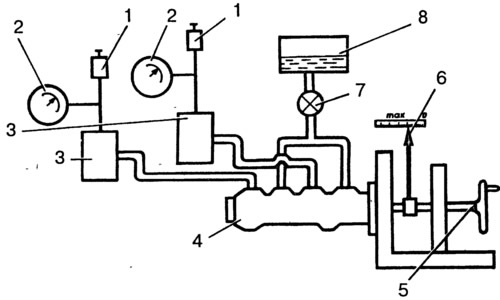
Pic. 6-11. Main cylinder leak test diagram:
1 - valve for pumping the stand; 2 - manometer; 3 - absorbing cylinder; 4 - main cylinder; 5 - flywheel; 6 - pusher offset indicator; 7 - crane; 8 - vessel.
Open valves 1 to bleed the stand and, by moving the master cylinder pistons several times to their full stroke length, bleed the system. Then close the valves 1. By rotating the flywheel 5, slowly move the master cylinder pistons until the pressure controlled by the pressure gauges 2 reaches 12.5 MPa (125 kgf/cm2). In this position, block the pusher of the master cylinder. The specified pressure must remain constant for at least 5 s.
In case of fluid leakage or reduction of the set pressure within 5 s, replace the cylinder piston seals.