




Contents: Cylinder head ↓ Valve seats ↓ Valves ↓ Valve guide bushings ↓ Springs ↓ Cylinder head mounting bolts ↓ Valve Levers ↓
Cylinder head
Wash the cylinder head thoroughly and clean the oil passages. Remove carbon deposits from the combustion chambers and from the surface of the exhaust passages with a wire brush.
Inspect the cylinder head. Cracks in any place of the cylinder head are not allowed. If you suspect that coolant has entered the oil, check the tightness of the cylinder head.
To check for leaks, close the openings of the cylinder head cooling jacket with the plugs included in the A.60334 tool kit (Fig. 2-45). Pump water into the cylinder head cooling jacket under a pressure of 0.5 MPa (5 kgf/cm²). No water leakage from the cylinder head should be observed within 2 minutes.
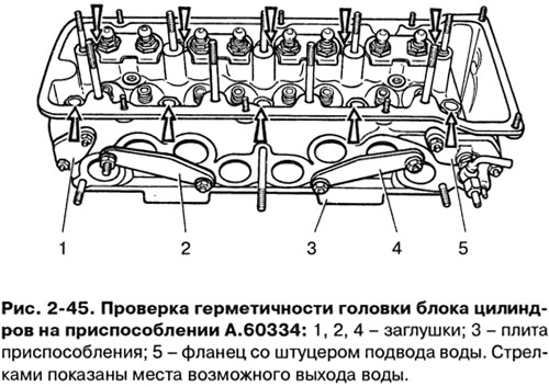
You can also check the cylinder head for leaks using compressed air, for which you should also install the plugs of the A.60334 device on the cylinder head. Place the cylinder head in a bath of water heated to 60-80°C and let it warm up for 5 minutes. Then supply compressed air under a pressure of 0.15-0.2 MPa into the head (1.5-2 kgf/cm²). Within 1-1.5 minutes, no air bubbles should be observed escaping from the head.
Valve seats
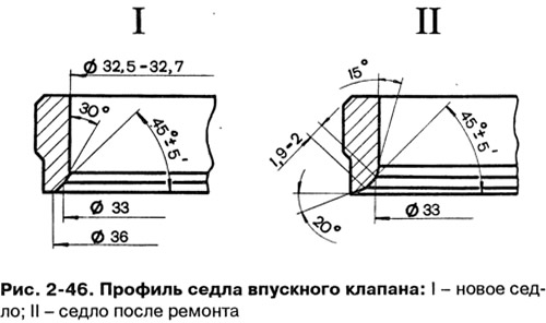
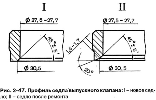
The shape of the valve seat chamfers is shown in Fig. 2-46 and 2-47. On the working chamfers of the seats (valve contact area) there should be no pitting, corrosion or damage. Minor damage can be eliminated by grinding the seats, removing as little metal as possible. Grinding can be done either manually or with a grinding machine.
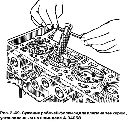
To grind the seats, place the cylinder head on a stand, insert the rod A.94059 into the valve guide sleeve and clean the seat chamfers from carbon deposits using countersinks A.94031 and A.94092 for exhaust valve seats and countersinks A.94003 and A.94101 for intake valve seats. The countersinks are placed on the spindle A.94058 and centered using the guide rod A.94059. These rods are available in two different diameters: A.94059/1 for intake valve guide sleeves and A.94059/2 for exhaust valve guide sleeves.
Place spring A.94069/5 on guide rod A.94059, install conical circle A.94078 for exhaust valve seats or circle A.94100 for intake valve seats on spindle A.94069, secure spindle in grinder and grind valve seat (Fig. 2-48).
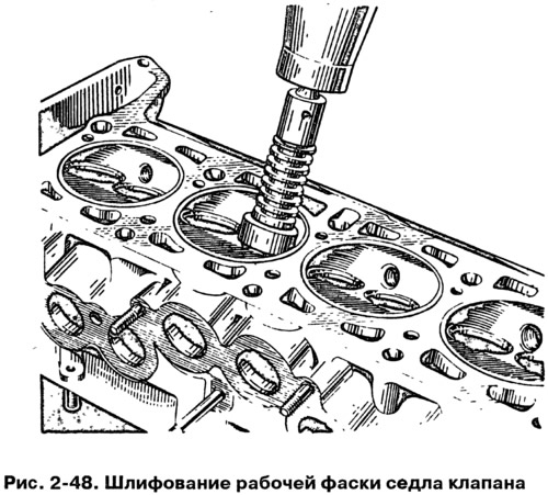
At the moment of contact of the wheel with the saddle the machine must be switched on, otherwise vibration will occur and the chamfer will be incorrect. It is recommended to correct the wheel more often with a diamond tool.
The material is posted on the website www.vazbook.ru
For the exhaust valve seats, bring the working chamfer width to the values shown in Fig. 2-46 using countersink A.94031 (angle 20°) and countersink A.94092, which removes work hardening on the inner diameter. Countersinks are placed on spindle A.94058 and, just as with grinding, are centered using rod A.94059.
At the inlet valve seats, bring the width of the working chamfer to the values shown in Fig. 2-47, first by processing the inner chamfer with countersink A.94003 (Fig. 2-49) until a diameter of 33 mm is obtained, and then the 20° chamfer with countersink A.94101 until a working chamfer of 1.9-2 mm width is obtained.
Valves
Remove carbon deposits from valves. Check if the stem is deformed and if there are any cracks on the plate. Replace the damaged valve.
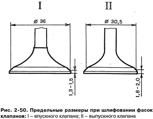
Check the condition of the valve working chamfer. In case of minor damage, it can be ground, maintaining the chamfer angle of 45°30'±5'. In this case, the distances from the lower plane of the valve plate to the base diameters (36 and 30.5 mm) must be within the limits shown in Fig. 2-50.
Valve guide bushings
Check the clearance between the valve guides and the valve stem by measuring the valve sleeve diameter and the guide bore.
Calculated clearance for new bushings: 0.022-0.055 mm for intake valves and 0.029-0.062 mm for exhaust valves; maximum permissible marginal clearance (when worn out) - 0.3 mm, provided that there is no increased noise from the valve timing mechanism.
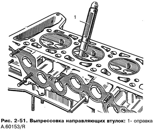
If the increased clearance between the guide bushing and the valve cannot be eliminated by replacing the valve, replace the valve bushings using the A.60153/R mandrel for pressing out and pressing in (Fig. 2-51).
Press in the guide bushings with the retaining ring fitted until it rests against the cylinder head body.
After pressing, ream the holes in the guide bushings using reamers A.90310/1 (for intake valve bushings) and A.90310/2 (for exhaust valve bushings).
Always replace the guide bushing oil deflector caps with new ones when repairing the engine.
Replace damaged valve stem seals on the removed cylinder head. Use mandrel 41.7853.4016 to press on the seals.
Springs
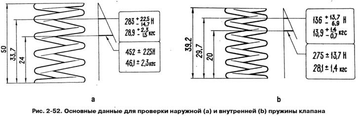
Make sure that there are no cracks in the springs and that their elasticity has not decreased by checking their deformation under load (Fig. 2-52).
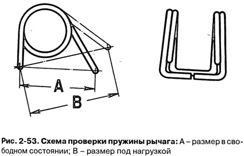
For lever springs (Fig. 2-53) size A (spring in free state) should be 35 mm, and the size B under load is 51-73.5 N (5.2-7.5 kgf) - 43 mm.
Cylinder head mounting bolts
When bolts are used repeatedly, they stretch out. Therefore, check if the length of the bolt shaft is longer (excluding head length) 120 mm, if it is more, then replace the bolt with a new one.
When replacing bolts, do not confuse them with bolts from other VAZ engines of the same type (2101, 21011, 2103, 2107, 2121), having similar bolts, but made of different steel.
The bolts of engines 21213 have a thread length of 70 mm (other engines have 30 mm), and the bolts 21213 do not have a distinctive mark (holes with a diameter of 7.5 mm) in the keyhole.
Valve Levers
Check the condition of the lever working surfaces that mate with the valve stem, the camshaft cam and the spherical end of the adjusting bolt. If these surfaces are scored or scratched, replace the lever with a new one.
If deformation or other damage is found on the lever adjusting bolt bushing or on the bolt itself, replace these parts as well.