




Camshaft
The bearing journals of the camshaft must not have any scoring, nicks, scratches, or aluminum drag from the bearing housings. The working surfaces of the cams must not have wear exceeding 0.5 mm, nor must scoring or cam wear in the form of faceting.
Install the camshaft with its outer journals on two prisms located on the surface plate and measure the radial runout of the middle journals with an indicator, which should be no more than 0.04 mm. If the runout exceeds the specified value, straighten the shaft on a straightening press.
Camshaft Bearing Housing
Wash and clean the bearing housing and oil supply channels.
Check the diameter of the holes in the bearings. If the gap between the camshaft journals and the bearings exceeds 0.2 mm (wear limit), replace the bearing housing.
The internal bearing surfaces must be smooth and free of burrs; if there is damage, replace the bearing housing. Check for cracks in the housing. If there are cracks, replace the camshaft bearing housing.
Tensioner
If the tensioner plunger is jammed in the housing, the chain tensioner must be disassembled. To do this, unscrew the cap locking nut 1 (fig. 2-56), push plunger 6 in as far as possible and tighten cap nut. File the edges of the housing hole in places B of the punching and remove plunger 6 with spring 4. Then unscrew the cap nut and remove rod 3 together with spring 7 and washer 5. Remove clamping cracker 8 from cap nut 1, removing spring ring 9.
Check for scoring on cracker 8, rod 3 and plunger 6, and for deep scratches on the mating surfaces of the shoe and plunger of the chain tensioner. Replace damaged parts.
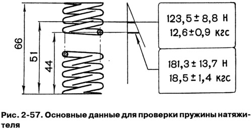
The elasticity of the tensioner spring must be within the limits indicated in Fig. 2-57; if the spring is less elastic, replace it.
Check for excessive wear on the shoe and guide; replace them if necessary.
The tensioner is assembled in the reverse order of disassembly. After installing the plunger, punch the housing 2 at three points B. In this case, the projections from the punching should not touch the surface A when the plunger moves,
Note: Some of the vehicles produced are equipped with tensioners that use a spring ring instead of a camshaft.
Camshaft drive chain
Wash the chain in kerosene, and then check the condition of its links. There should be no chips, cracks or other damage on the rollers and cheeks.
When the engine is running, the chain stretches. It is considered operational as long as the tensioner provides its tension, i.e. if the chain has stretched no more than 4 mm.
Check the chain extension using device 67.7824.9521 (Fig. 2-58), which has two stepped rollers 1, onto which the chain is placed. Using counterweight 3, the chain is stretched with a force of 294 N (30 kgf) or 147 N (15 kgf). Adjusting nut 2 ensures that the counterweight axis is parallel to the base of the device.
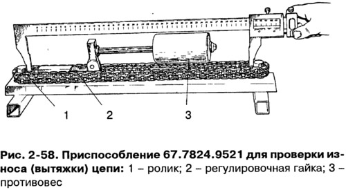
Stretch the chain with a force of 294 N (30 kgf), placing the counterweight in the extreme right position, then reduce the force by 147 N (15 kgf), moving the counterweight to the extreme left position. Repeat both operations once more and determine the chain stretch by the distance L (Fig. 2-59) between the roller axes. By measuring the distance between the roller diameters d with a caliper and adding the diameter d to it, you get the distance L between the roller axes.
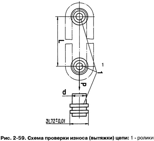
For a new chain, the distance L between the roller axes is 495.4-495.8 mm; if the chain has stretched to 499.5 mm, it should be replaced.
Before installing on the engine, lubricate the chain with engine oil.