




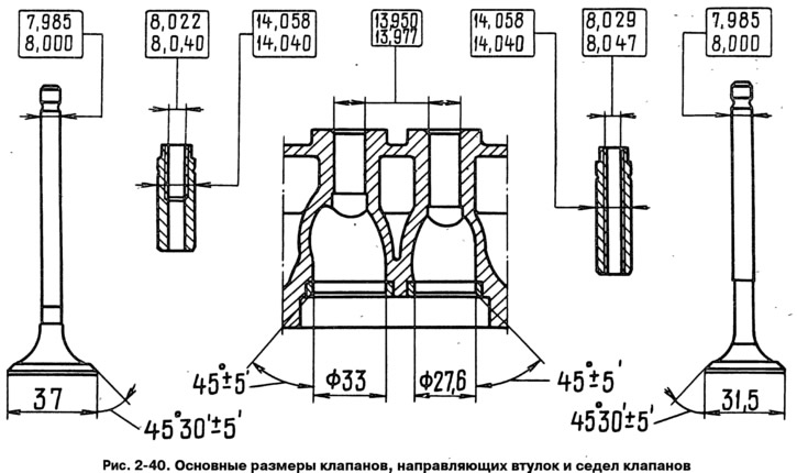
The cylinder head is cast from an aluminum alloy and has pressed-in cast iron valve seats and guide bushings. The upper part of the bushings is sealed with metal-rubber oil-deflecting caps 3 (Fig. 2-41).
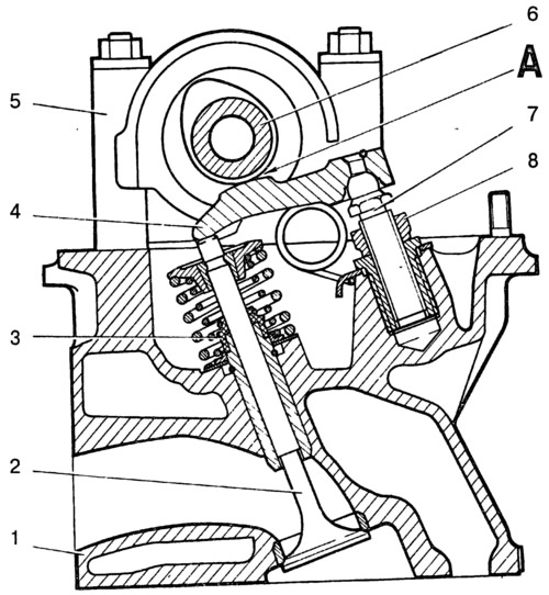
Fig. 2-41. Section of the cylinder head along the exhaust valve:
1 - cylinder head; 2 - valve; 3 - oil deflector cap; 4 - valve lever; 5 - camshaft bearing housing; 6 - camshaft; 7 - adjusting bolt; 8 - adjusting bolt lock nut; A - clearance between the lever and the camshaft cam.
Guide bushings are supplied as spare parts with an outer diameter increased by 0.2 mm.
The bearing housing 5 is fixed to the cylinder head, in which the camshaft 6 is located.
Valve drive mechanism
Valves 2 are actuated by the camshaft cams through levers 4. One end of the lever presses on the valve stem, and the other end rests on the spherical head of the adjusting bolt 7, which regulates the clearance A in the valve mechanism.