
Cut down with a thin sharpened chisel or cut off with a grinder along the connection wing:
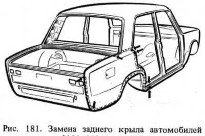
- with an arch of a back wheel on a bend (pic. 181), departing from the edge of the wing 12-15 mm;
- with spare wheel floor (or fuel tank) along the bend, stepping back from the edge of the wing 12-15 mm;
- with the tailgate panel, stepping back from the connection line 2 mm;
- with rear window crossbar panel, 2 mm away from the edge of the wing bend;
- with the rear part of the sidewall along the bend, departing from the edge of the wing 15-20 mm.
The angle of the wing connection with the rear panel of the upper part of the horizontal line is cut down, stepping back from the edge of the angle 15 mm. With a drill with a diameter of 6-7 mm, drill out the resistance welding points at the junction of the wing with the side roof panel and disconnect the wing. The remaining strips of the wing are removed, the deformed edges are straightened and the seats of the body elements and the new wing are cleaned.
They adjust the new wing at the landing site, grab it with quick-release grips and check the external clearances (see fig. 178, 179). Welded by gas welding to the lower and rear of the sidewall, to the rear window cross member panel, roof side panel, to the tail panel connection elbow, to the floor of the spare wheel (fuel tank) solder L62 or L68. On fig. 181 places of gas welding are shown by arrows. The landing of the wing relative to the mating surfaces is checked and it is welded by contact welding with a step of 40-50 mm. The wing amplifiers are welded by gas welding. In the absence of a contact welding machine, gas welding by flashing the edges with an intermittent seam 20 mm long every 30 mm with L68 solder is allowed. In the doorway, welding of the wing is allowed by a semi-automatic device in a carbon dioxide environment.