The deformation of the compression buffer bracket can be checked as shown in Figure 188. If the size "V" less than 32 mm, the bracket is changed. To do this, remove the front wheel, clean the surface of the flange from the mastic, drill out all the welding points (drill diameter 6 mm) to the depth of the metal thickness of the bracket and disconnect the bracket from the rack. In case of small dents in the places where the bracket is welded, they are straightened with a punch through the middle hole in the mudguard from the side of the engine compartment. The surface of the rack is cleaned, a new bracket is welded along the perimeter by electric arc welding with an E-34 or E-32 electrode with a diameter of 1.6-2.0 mm with an intermittent seam and the weld is painted.
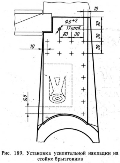
The center of the buffer hole in the bracket must be 97 mm higher than the axis of the upper arm of the front suspension, which corresponds to a distance of 9.5 mm from the edge of the bracket to the curved surface of the rack.
In case of deformation of the rack with deformation of the side surfaces, the bracket is removed and the rack is straightened. Manufactured locally from sheet steel 1.5 mm thick (to reinforce the rack) and drill holes in it with a diameter of 6-8 mm, maintaining the dimensions shown in Fig. 189. Clean the surface of the rack, weld the pad by electric arc welding around the perimeter and holes. Then the buffer bracket is welded, maintaining the dimensions indicated above.