
Disassembly
If only one part needs to be replaced, the cylinder head may not be completely disassembled and only what is needed for replacement can be removed. The cylinder head is completely disassembled in the following sequence.
Removing cover 5 (pic. 38) with gasket 7, install cylinder head 1 on a stand, unscrew the nuts and remove the carburetor with a spacer, the carburetor heat shield, and then the intake and exhaust pipes (at the same time the warm air intake is removed).
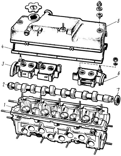
Pic. 38. Parts and assemblies of the cylinder head
Remove the outlet pipe of the engine cooling jacket. Unscrew the coolant temperature indicator sensor, oil pressure warning lamp sensor and spark plugs. Unscrew the nuts and remove the fuel pump with gaskets, spacer and pusher. Disconnect the auxiliary unit housing from the cylinder head.
Remove bearing housings 3 and 6 of the camshaft. Take out the camshaft 2 from the bearing beds of the cylinder head and remove the oil seal 7 from it.
Remove the pushers from the holes in the cylinder head (pic. 39) valves with shims K). The valves are released from crackers 9 by compressing the valve springs with tool 67.7823.9505 (pic. 40). Remove the springs with plates. Turn the cylinder head and remove the valves from the underside. Remove the oil seals from the guide bushings and spring washers.
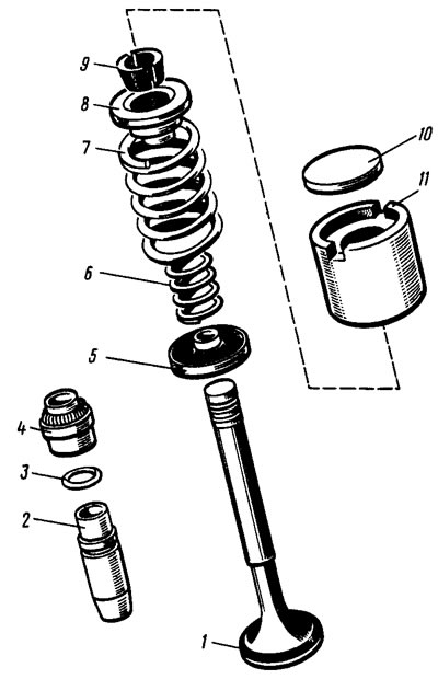
Pic. 39. Valve mechanism details: 1 - valve; 2 - guide sleeve; 3 - retaining ring; 4 - oil deflector cap; 5 - spring washer; 6 - internal spring; 7 - outer spring; 8 - a plate of springs; 9 - crackers; 10 - adjusting washer; 11 - pusher | 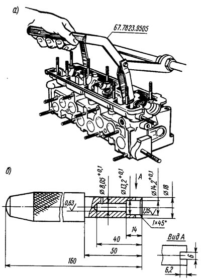
Pic. 40. Equipment for assembling the valve mechanism: a - fixture 67.7823.9505 for compressing springs; b - mandrel 41.7853.4016 for installing oil seals |
Assembly
Lubricate the valves and new valve stem seals with engine oil (old ones are not allowed). Having installed the support washers of the springs, the caps are pressed onto the valve guides with the mandrel 41.7853.4016. Insert the valves into the guide bushings, install the springs and valve plates. Compressing the springs with tool 67.7823.9505 (see fig. 40), install the valve cotters. Insert valve tappets with shims into the holes of the cylinder head.
Check if the locating sleeves of the camshaft bearing housings are in place (put on studs in fig. 38). They clean the mating surfaces of the cylinder head and bearing housings from the remnants of the old gasket, dirt and oil. Lubricate the bearing journals and camshaft cams with engine oil and place it in the cylinder head bearings in such a position that the cams of the 1st cylinder are directed upwards.
On the surfaces of the cylinder heads mating with the bearing housings, in the area of the extreme camshaft bearings, SUPER THREE BOND No.50 sealant or a domestic-made KLT-75T sealant similar to it is applied. It must be borne in mind that it is allowed to start the engine no earlier than 1 hour after applying the sealant.
Install the bearing housings and tighten the nuts of their fastening in two steps (see above «Removal and installation of a camshaft»). Using mandrel 67.7853.9580, a new camshaft oil seal is pressed in, having previously lubricated it with engine oil.
Install the outlet pipe of the cooling jacket with a gasket and the housing of auxiliary units with a sealing ring. In accordance with the instructions of Sec. «Removal and installation of the fuel pump» install a heat-insulating spacer with gaskets, a pusher and a fuel pump.
Put gaskets on the cylinder head studs and install the exhaust manifold, fix it with a central nut, and then install the intake manifold. Fix them together with the intake 4 (see fig. 35) warm air. Install the carburetor heat shield, spacer and carburetor. Fix it with nuts and close the carburetor with a technological plug.
Spark plugs and sensors for the coolant temperature indicator and oil pressure warning lamp are wrapped in the cylinder head.