




Wheel cylinders
Disassemble the wheel cylinders, for which remove the protective caps 1 (Fig. 6-20) and pistons 2, take out the seals 3, support cups 5 and spring 7. Then unscrew the nipple 6. Check the cleanliness of the working surfaces of the cylinder and pistons. The surfaces must be completely smooth, without roughness, to prevent fluid leakage and premature wear of the seals and pistons. Eliminate defects on the cylinder mirror by lapping or grinding. However, an increase in the internal diameter of the cylinder is not allowed.
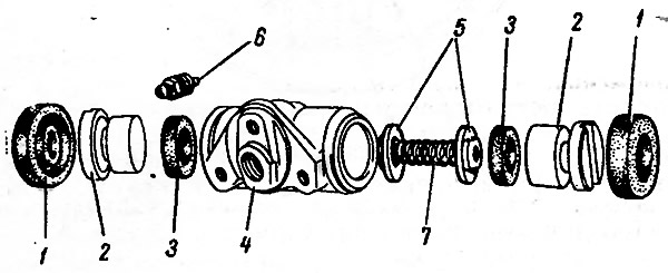
Fig. 6-20. Wheel cylinder parts: 1 - protective cap; 2 - piston; 3 - seal; 4 - wheel cylinder housing; 5 - spring cups; 6 - air release nipple; 7 - spring
Replace the seals 3 with new ones. Check the condition of the protective caps 1 and replace them if necessary.
[The information can be read on the website: www.VAZbook.ru]
Check the condition of spring 7. Its length in a free state should be 34 mm, under a load of 34.3±1.96 N (3.5±0.2 kgf) - 17.8 mm, replace it if necessary.
Before assembly, generously lubricate all parts with brake fluid. Install parts in the reverse order of disassembly. After assembly, check the piston movement, which should be smooth, without jamming.
Pads
Check the pads carefully for damage or deformation.
Check the elasticity of the tension springs, both upper and lower; replace them with new ones if necessary.
The springs must not have residual deformations when stretched: the lower ones - with a force of 343 N (35 kgf), the upper ones - 412 N (42 kgf).
Check the cleanliness of the linings, if dirt or traces of grease are found, thoroughly clean the linings with a metal brush and wash with white spirit, in addition, check for grease or oil leaks inside the drum; please fix the problems.
Replace the pads with new ones if the thickness of the linings has become less than 1.5-2 mm.
Brake drums
Inspect them. If there are deep scratches or excessive ovality on the working surface, ream the drums on the machine.
Then use a lathe to grind the drums with fine-grained abrasive blocks. This increases the durability of the pads and improves the uniformity and effectiveness of braking.
The maximum allowable increase in the nominal drum diameter (250 mm) after boring and grinding is 1 mm. The limits of this tolerance must be strictly observed. Otherwise, the strength of the drum and the braking efficiency are impaired.
Checking the rear brake wheel cylinders on a stand.
Install the cylinder on the stand, connect the pipeline from the pressure gauges to it (Fig. 6-21) and bleed the system.
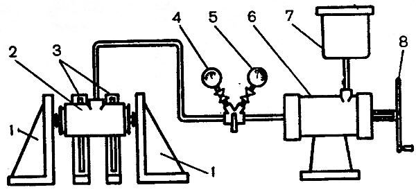
Fig. 6-21. Rear brake wheel cylinder test diagram: 1 - piston stops; 2 - test cylinder; 3 - cylinder bracket; 4 - low pressure gauge; 5 - high pressure gauge; 6 - cylinder for creating pressure; 7 - vessel; 8 - flywheel
Adjust stops 1 so that the wheel cylinder pistons rest against them.
Check for fluid leaks. Connect a low pressure gauge; slowly rotating the flywheel of the drive cylinder control, set the fluid pressure to 0.05 MPa (0.5 kgf/cm²).
Make sure that the set pressure is maintained for 5 min. Repeat the test similarly at a pressure of 0.1-0.2-0.3-0.4-0.5 MPa (1-2-3-4-5 kgf/cm²).
Reduce the pressure and connect a high-pressure gauge. Following the specified rules, repeat the tests at a pressure of 5-10-15 MPa (50-100- 15G kgf/cm²).
Pressure loss due to fluid leakage through sealing elements, pipe connections, fluid inlet fittings or through casting pores is not permitted.
A slight (no more than 0.5 MPa (5 kgf/cm²) over 5 min) decrease in pressure is allowed, especially at higher pressures, due to shrinkage of the seals.