




Disassembly
Loosen the nut on the lower contact bolt of the traction relay and disconnect the stator winding terminal from it. Loosen the nuts securing the traction relay and remove it.
Loosen the screw securing the protective clamping tape on cover 10 on the collector side and remove tape 9 with the gasket. Unscrew the screws securing the brush terminals and remove the brushes. For starter 35.3708, remove the lock washer from the rear end of the shaft.
Unscrew the nuts of the tie rods 15 (fig. 7-16), unscrew the studs and remove cover 1 from the drive side together with anchor 16.
Disconnect the cover on the collector side from the housing. Remove the rubber plug 2 of the lever from the cover on the drive side, unpin and remove the axle of the lever 3 of the starter drive, remove the lever and anchor from the cover
To remove the drive from the anchor, remove the retaining ring from under the stop ring 21 (fig. 7-13). The drive is disassembled after removing the lock washer from the coupling hub.
After disassembling, blow out the parts with compressed air and wipe them dry.
Technical condition check and repair
Anchor. Check with a megohmmeter or with a lamp powered by 220 V to see if the armature winding is shorted to ground.
Voltage is supplied through the lamp to the collector plates and to the anchor core. The lamp burning indicates a short circuit of the winding or the collector plate with the "ground". When checking, the megohmmeter should show a resistance of at least 10 kOhm. Replace the anchor that has a short circuit with the "ground".
Use a special device to check whether there are short circuits between the armature winding sections or the collector plates, and whether there are breaks where the winding section leads are soldered to the collector plates.
Inspect the working surface of the commutator and check its runout relative to the shaft journals (Fig. 7-17). Clean the contaminated or burnt surface with fine-grained sandpaper. If the surface damage is significant or its runout is greater than 0.06 mm, turn the commutator on a lathe, removing as little metal as possible. The minimum diameter to which the commutator can be turned is 36 mm. After turning, polish the commutator with fine-grained sandpaper.
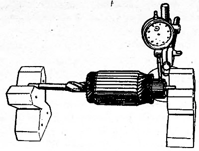
Fig. 7-17. Checking the collector runout using an indicator
Check the runout of the core relative to the shaft journals. If it is more than 0.08 mm, replace the anchor.
Check the condition of the spline and journal surfaces of the anchor shaft. They should be free of burrs, nicks and wear. If yellow marks from the gear bushing appear on the shaft surface, remove them with fine-grained sandpaper, as they may cause the gear to jam on the shaft.
Drive. The gear teeth should not have significant wear. If there are nicks on the entry part of the teeth, then grind them with a fine-grained emery wheel of small diameter. The gear should easily rotate relative to the clutch hub, but only in the direction of rotation of the anchor when starting the engine. If the drive parts are damaged or significantly worn, replace the drive with a new one.
Stator. Check with a megohmmeter or a lamp powered by 220 V to see if the starter winding is shorted to ground. Voltage is supplied through the lamp to the common terminal of the winding and to the starter housing. If the lamp lights up or the megohmmeter shows resistance less than 10 kOhm, and also if the winding shows signs of overheating (blackening of insulation), replace the winding.
To replace the stator winding coils, remove the poles by unscrewing the mounting screws with a drill-screwdriver. Before removing the poles, make marks on the housing and poles so that after assembly they can be returned to their original position.
(The original source is located on the website www.VazBook.ru)
It is recommended to heat the winding to about 50°C before installation to make it flexible and to facilitate laying on the poles. The poles must be tightened with screws until they stop, so that the air gap between the anchor and the poles is maintained at the original dimensions: 0.38 mm when checked with a feeler gauge.
After assembly, check the internal diameter between the poles, which should be 67.80-67.97 mm. In addition, using a 67.66 mm diameter plug gauge, check the concentricity of the housing and poles. The gauge should freely enter and rotate between the poles when seated on the inner surface of the housing. If this does not happen, repeat the assembly, since it was probably done incorrectly.
Boring of poles is not permitted.
Lids. Check for cracks on the caps. If there are any, replace the caps with new ones. Check the condition of the cap bushings. If they are worn, replace the caps as a whole or just the bushings. After pressing in, unfold the new bushings to 12.015+0,15 mm. To replace the bushing in the cover on the manifold side, first remove the plug, and after pressing the bushing, install the plug in place and punch it at three points.
Check the reliability of the fastening of the brush holders on the cover from the collector side. The brush holders of the positive brushes should not have a short circuit with the "ground". The brushes should move freely in the grooves of the brush holders. Replace brushes that are worn down to 12 mm in height with new ones, having first ground them to the collector.
Check the spring pressure on the brushes using a dynamometer, which for new brushes should be 9.8±0.98 N (1±0.1 kgf) and, if necessary, replace the springs with new ones.
Traction relay. Check the ease of movement of the relay anchor. Check with an ohmmeter whether the relay contact bolts are closed by the contact plate. If the contact bolts do not close, disassemble the relay and clean the contact bolts with fine-grained sandpaper or a flat velvet file. If the contact bolts are significantly damaged at the point of contact with the contact plate, they can be turned 180°.
Assembly
Before assembly, lubricate the helical splines of the anchor shaft and the overrunning clutch hub with engine oil (M-10GI). Lubricate the bushings of both covers and the gear with engine oil, and the drive carrier ring with LITOL-24 consistent grease.
Before assembly, check the axial free play of the anchor shaft by first assembling the covers, housing and anchor and tightening the nuts of the tie rods. In this case, the anchor may be without a drive, and the cover 1 (fig. 7-16) without a lever. The axial free play of the shaft should be within 0.07-0.7 mm. The change in the free play value is achieved by selecting the number or thickness of the adjusting washers 20. In the starter 35.3708, the adjusting washers are located on both sides of the cover 10 on the collector side, and the free play of the shaft should be no more than 0.5 mm.
Having selected the adjusting washers, proceed to assembly, which is performed in the reverse order of disassembly. After assembly, check the starter on the stand.