




Contents: Current sources ↓ Current consumers ↓
In a car, electrical energy is used to start the engine, ignite the working mixture, light, signal, power control devices, additional equipment, etc.
The electrical equipment of a car includes sources and consumers of electric current. A single-wire system is used to connect sources and consumers of current. The second wire is the car's ground (its metal parts), to which the negative poles of electrical devices are connected. Electrical devices are powered by direct current with a voltage of 12 V.
A simplified diagram of the general electrical circuit of the electrical equipment system and the connection of devices without taking into account their actual location on the vehicle is shown in Fig. 16.
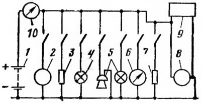
Fig. 16. Schematic diagram of electrical equipment:
1 - battery; 2 - starter; 3 - ignition system devices; 4 - lighting system devices; 5 - alarm system devices; 6 - control electrical devices; 7 - additional equipment, 8 - generator; 9 - voltage regulator; 10 - ammeter.
Current sources
The sources of current in the car are the generator and the battery. The voltage regulator is connected to the sources of current.
The original is available on the website (www.VAZbook.ru)
Generator converts mechanical energy received from the engine into electrical energy. The generator supplies power to all consumers of electric current when the engine is running. The Niva automobile is equipped with an alternating current generator G-221 (Fig. 17). The main parts of the generator are the stator 12 with a fixed winding in which alternating current is induced, and the rotor 11, which creates a movable magnetic field. The generator rotor is mounted in two ball bearings. It is driven into rotation through the generator pulley using a V-belt from the engine crankshaft.

Fig. 17. Generator G-221:
1 - back cover: 2 - rectifier block; 3 - protective cover; 4 - contact bolt extension; 5 - contact bolt; 6 - wires; 7 - brush holder with brushes; 8 - pulley with fan; 9 - ball bearing; 10 - front cover; 11 - rotor; 12 - stator; 13 - buffer bushing; 14 - bushing; 15 - pressure sleeve; 16 - tie bolt.
The generator has a rectifier block 2, which converts alternating current into direct current. Cooling of the generator is carried out by the generator pulley fan.
Battery converts chemical energy into electrical energy. The battery supplies electrical current to consumers when the engine is not running. The car is equipped with a 6ST-55P battery. The battery is lead-acid, starter, with a voltage of 12 V and a capacity of 55 Ah.
The battery case is made of acid-resistant plastic and is divided by partitions into six sections. Each section contains a separate element consisting of positive and negative plates and separators (separators) between them. The elements have a voltage of 2 V and are connected in series with each other by bridges. The battery case is closed with a plastic cover common to all elements. The cover is welded by heat welding along the periphery to the outer walls of the case. The connections of the cover with the partitions of the case are sealed during assembly with a sealant, which eliminates the overflow of electrolyte from one section to another. For each section, the cover has a threaded hole with a plug for filling and monitoring the electrolyte level. The plugs are equipped with holes for connecting the internal cavity of the battery with the atmosphere.
The battery has two terminals; positive and negative.
Voltage regulator maintains a constant voltage of the current generated by the generator at a variable speed of rotation of the engine crankshaft. The car uses a PP-380 voltage regulator. This is a two-stage electromagnetic regulator of the vibration type.
When the generator voltage increases to 13-14 V, additional resistance is included in the excitation winding circuit. This is the first stage of generator voltage regulation. When the voltage increases above 14 V, the generator excitation winding is shorted to ground. This is the second stage of voltage regulation. As a result, the generator voltage is regulated within the specified limits.
Current consumers
The consumers of current in a car are the starter, ignition system, and lighting system (external and internal), alarm system (sound and light), control electrical devices and additional equipment.
The starter ensures that the crankshaft rotates at the speed required to start the engine.
The car is equipped with a ST-221 starter (Fig. 18). The starter is a four-pole, four-brush DC electric motor with mixed excitation, with electromagnetic engagement of the drive gear and remote control.
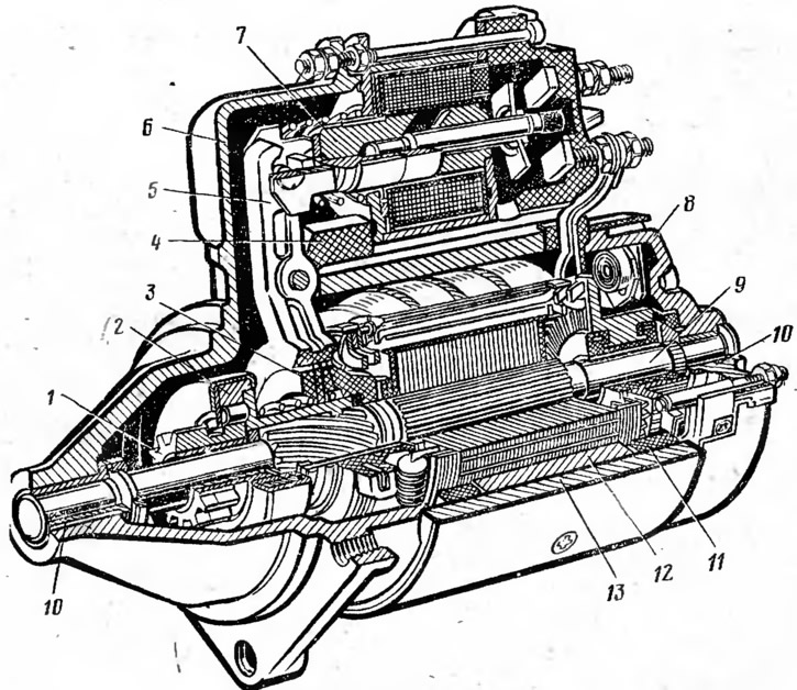
Fig. 18. Starter ST-221:
1— drive gear; 2 - freewheel clutch; 3 - leash ring; 4 - rubber plug; 5 - drive lever; 6 - front cover; 7 - traction relay; in - back cover; 9 - anchor; 10 - bushing; 11 - winding of a hundred mountain; 12 - stator pole; 13 - body.
In the housing 13 of the starter there are four poles 12. Two of them with excitation windings connected in series with the armature winding 9, and two - in parallel. The starter armature shaft is installed in two bushings 10, located in covers 6 and 8. At the front end of the armature shaft, a starter drive is installed, consisting of a freewheel roller clutch 2 and a drive gear 1, which can move along the shaft splines. The freewheel clutch transmits rotation from the starter armature shaft to the flywheel when starting the engine and prevents the transmission of rotation from the flywheel to the starter armature after starting the engine. A traction relay 7 is installed on the front cover 6 of the starter. When starting the engine, the relay ensures that the drive gear 1 is engaged with the flywheel ring and the electrical circuit of the starter windings is connected to the storage battery. On the rear cover 8 of the starter, brush holders with four brushes are fixed, which are pressed by springs to the armature collector.
When the starter is running, current flows through its windings. A strong magnetic excitation field is created around the poles. This field interacts with the magnetic field of the anchor winding and causes the anchor to rotate, which is transmitted to the flywheel via the starter drive.
Ignition system serves to ignite the working mixture in the cylinders in accordance with the order and operating mode of the engine.
The ignition system includes: an ignition coil, an ignition distributor including a low-voltage circuit breaker and a high-voltage circuit breaker, spark plugs and an ignition switch.
The basic diagram of the ignition system of the engine of the Niva VAZ-2121 car is shown in Fig. 19.
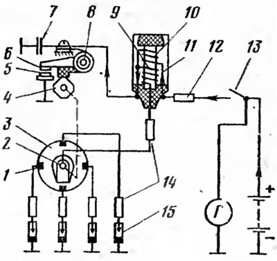
Fig. 19. Schematic diagram of the ignition system:
1 - contact; 2 - rotor; 3 - high voltage current distributor; 4 - cam; 5 - fixed contact; 6 - movable contact; 7 - capacitor; 8 - low voltage circuit breaker;, 9 - secondary winding; 10 - primary winding; 11 - ignition coil; 12 - additional resistance; 13 - ignition switch; 14 - overwhelming resistance; 15 - spark plug.
The ignition system diagram includes: two electric circuits - a low-voltage circuit (primary) and a high-voltage circuit (secondary). The primary circuit includes: ignition switch 13, additional resistor 12, primary winding 10 of the ignition coil, low-voltage circuit breaker 8 and capacitor 7. The secondary circuit includes: secondary winding 9 of the ignition coil, high-voltage current distributor 3 and spark plugs 15.
When the ignition switch is on and contacts 5 and 6 of the low-voltage circuit breaker are closed, current from the battery or generator flows through the low-voltage circuit. Passing through the primary winding of the ignition coil, the current creates a strong magnetic field. When the contacts of the circuit breaker 8 open, (cam 4 runs with its protrusion onto the lever with contact 6) the current in the low voltage circuit is interrupted and the created magnetic field disappears. In this case, the magnetic field crosses the secondary winding of the ignition coil and induces a high voltage current in it. The high voltage current is supplied to the rotor 2 of the ignition distributor, which rotates together with the cam 4. At the moment of opening the contacts of the breaker, the high voltage current is supplied to one of the contacts 1 of the ignition distributor, which are connected to the spark plugs 15. A spark discharge between the electrodes of the spark plug occurs in the engine cylinder in which at that time the compression of the working mixture ends, i.e. in the sequence corresponding to the order of engine operation (1-3-4-2).
Ignition coil converts low voltage current (12 V) into high voltage current, which can reach 16-20 kV.
The car uses the B-117A ignition coil. The secondary winding is wound on the ignition coil core, which consists of thin sheets of electrical steel, and has a large number of turns (~21,000) of insulated copper wire with a diameter of ~0.07 mm. The primary winding has ~308 turns of insulated copper wire with a diameter of ~0.57 mm. The inner cavity of the housing is filled with transformer oil, which improves the cooling and insulation of the windings! ignition coil. The coil cover contains terminals for the primary and secondary windings. Outside the coil housing there is an additional resistor, connected in series with the primary winding and automatically regulating the current in the winding depending on the engine crankshaft speed.
Distributor performs closing and opening of low voltage current and distribution of high voltage current among engine cylinders.
The car uses the P125-B ignition distributor (Fig. 20). The ignition distributor consists of a breaker and a distributor installed in one common housing. In the housing 3 of the distributor, shaft 1 of the breaker cam drive, rotor 14 of the distributor and the centrifugal regulator, which automatically changes the ignition advance angle depending on the engine crankshaft speed, is also installed. When shaft 1 rotates, cam 8 opens contacts 7 of the breaker. Rotor 14 and centrifugal regulator 20 rotate together with the shaft, the weights of which, overcoming the force of springs 21, diverge under the action of centrifugal forces. The weights of the centrifugal regulator are connected to the breaker cam and, as the shaft speed increases, they turn the cam relative to the shaft, changing the ignition advance angle. Depending on the octane number of the fuel used, the ignition advance angle is changed manually using the octane corrector eccentric 9, connected via a rod to the movable plate 24, on which the breaker contacts 7 are installed.
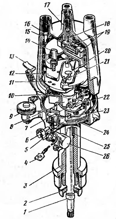
Fig. 20 Ignition distributor R-125B:
1 - shaft; 2 - oil-deflecting coupling: 3 - housing; 4 - low voltage wire; 5 - fixed breaker plate; 6 - oiler; 7 - breaker contacts; 8 - cam; 9 - octane corrector eccentric; 10 - cam felt; 11 - cam follower plate; 12 - centrifugal regulator weight; 13 - latch; 14 - rotor; 15 - lid; 16 - cover electrode; 17 - central electrode; 18 - carbon contact; 19 - rotor electrode; 20 - centrifugal regulator; 21 - weight spring; 22 - breaker lever; 23 - fixed contact holder; 24 - movable breaker plate; 25 - Shaft sleeve; 26 - capacitor.
The ignition distributor cover 15 has four side electrodes 16 and a central electrode 17. The side electrodes are connected to the spark plugs by high-voltage wires, and the central electrode is connected to the ignition coil. The high-voltage current flows through the central electrode to the current-distributing plate of the rotating rotor 14 and through it to the side electrodes in accordance with the engine operating order.
Spark plug provides an electric spark in the engine cylinder. The ignition system of the car engine uses A17DV spark plugs. The spark plug (Fig. 21) is non-separable. The metal housing 4 has a rolled-in core, which is a ceramic insulator 2, inside which the contact rod 1 and the central electrode 6 are located. The spark plug housing has an external thread 5, with the help of which the spark plug is attached to the cylinder head. The side electrode 7 is connected to the housing. The tip connecting the spark plug to the high-voltage wire has a suppressor resistance, which reduces radio interference created by the ignition system.
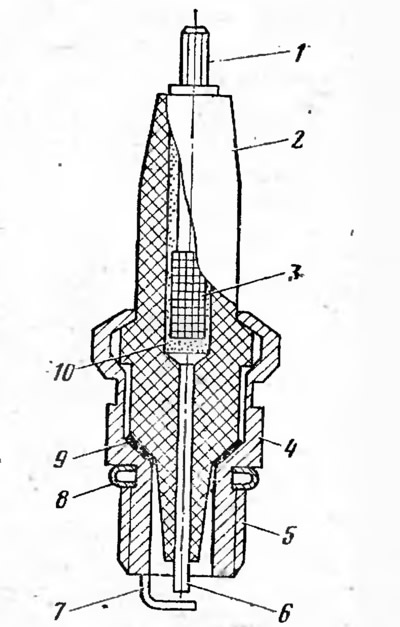
Fig. 21. Spark plug A17DV:
1 - contact rod; 2 - insulator; 3 - knurling; 4 - body; 5 - thread; 6 - central electrode; 7 - side electrode; 8 - gasket; 9 - washer; 10 - sealant.
Ignition switch. switches on and off the ignition system, starter, control and measuring devices and other instruments.
The vehicle is equipped with a VK-347 ignition switch (Fig. 22). The switch has an anti-theft device. The switch mechanism is secured in the housing 1 using a locking ring 12. It consists of a panel 11 with plug clamps 13 and contacts 10, a cam 9 and a rotor 7 with contact plates 8. The cam and rotor of the switch are turned by the key of the locking device 3. The locking rod 6, under the action of the spring 2, enters the groove of the steering shaft and locks the shaft when the key, set to the "parking" position, is removed from the locking device of the switch. The projection 5 serves for the correct installation of the ignition switch in the steering column.
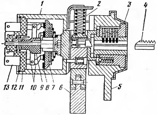
Fig. 22. Ignition switch VK-347:
1 - body; 2 - spring; 3 - locking device; 4 - key; 5 - mounting protrusion; 6 - locking rod; 7 - rotor; 8 - contact plates; 9 - cam; 10 - contacts; 11 - panel; 12 - retaining ring; 13 - clamps.
Lighting system ensures vehicle operation in poor visibility conditions (at night, in fog, etc.). The system includes external and internal lighting. The lighting system includes: headlights, front and rear lights, license plate lights, interior lights, instrument panel and engine compartment lights, fuses and switches.
Headlights illuminate the road ahead of the vehicle in poor visibility conditions (at night, in fog, etc.). The vehicle uses a two-headlight lighting system with round headlights of the FG-140 type. In the housing 5 of the headlight (Fig. 23) a holder 6 of the optical element 1 is installed. The optical element of the headlight, consisting of a reflector 7, a diffuser 2 and a lamp 9, is attached to the holder by a rim 3 using screws 10. The headlight lamp is a two-filament lamp with a power of 45 W for high beam and 40 W for low beam. Screws 4 and 11 allow changing the position of the holder 6, and with it the optical element in the vertical and horizontal planes when adjusting the headlight beam.
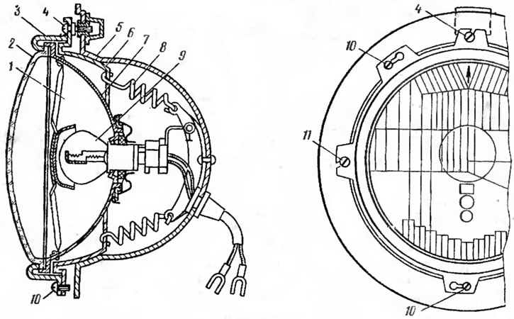
Fig. 23. Headlight FG 140:
1 - optical element: 2 - diffuser; 3 - rim; 4, 11 - adjusting screws; 5 - body; 6 - optical element holder; 7 - reflector; 8 - spring; 9 - lamp; 10 - screw.
Front lights they are used to indicate the dimensions of the vehicle, parking lights and light signals when maneuvering.
The front light is two-section, rectangular. The cast housing of the light contains two single-filament lamps. The 5-watt lamp is used to indicate the dimensions of the car, and the 21-watt lamp is used to signal when the car is maneuvering. The front light diffuser is plastic, monolithic, two-color. The outer part of the diffuser is orange and is used to signal when maneuvering, and the inner part is colorless and is used to indicate the dimensions of the car.
Rear lights they are used to indicate the dimensions of the vehicle and provide light signaling when turning, braking and reversing.
The rear light has a rectangular shape. The rear light housing has four sections, which contain three 21 W lamps and one 5 W lamp. The first three are brake light, turn signal and reversing light lamps, and the last one is a parking light lamp. The light housing is covered with a diffuser. The diffuser is plastic, monolithic, multi-section, three-color. The outer part of the diffuser is orange and serves to signal when the car is maneuvering. The central section is colorless and serves to signal when reversing. The remaining sections of the diffuser are red and are intended to signal when braking and to indicate the dimensions of the car.
Alarm system ensures the safety of the vehicle. The system includes light and sound signaling.
To the light signaling includes front, rear, side direction indicators and their switch, as well as brake lights (stop signal), reverse lights and their switches. The front turn signals are located in the front lights of the car. The rear turn signals, brake lights and reverse lights are located in the rear lights of the car. The side turn signals are located on the front fenders of the car body.
Sound signals are related to sound alarms. The sound signal notifies pedestrians and drivers of vehicles about the presence of a vehicle, if necessary. Two electric vibration, hornless noise-type sound signals are installed on the vehicle: one high-pitched and the other low-pitched. The signals are tuned to a harmonic chord and operate simultaneously. The current passing through winding 8 of the signal (Fig. 24) magnetizes core 7, which attracts anchor 10 and causes deflection of elastic steel membrane 1. In this case, the anchor acts on elastic plate 5 and opens contacts 2. The current in winding 8 is interrupted, and core 7 is demagnetized. Membrane 1 returns to its original position and contacts 2 close. The signal operation is repeated with a contact vibration frequency of 200-400 Hz. The air vibrations caused by the membrane create the sound, and the diffuser (resonator) 3 ensures its melodic sound. The corresponding tone and timbre of the sound depends on the thickness and diameter of the membrane, as well as the diameter of the resonator. In a high-tone signal, the membrane is thinner than in a low-tone signal.
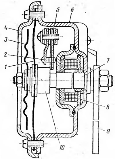
Fig. 24. Sound signal:
1 - membrane; 2 - contact; 3 - diffuser; 4 - ring; 5 - plate; 6 - body; 7 - core; 8 - winding; 9 - signal mounting plate; 10 - anchor.
Control and measuring instruments are designed to monitor the condition and operation of individual systems and mechanisms of the vehicle.
The control and measuring devices include: an ammeter measuring the strength of the charging and discharging currents, fuel level indicators in the tank, coolant temperature in the cooling system and oil pressure in the engine lubrication system. In addition, there are a number of control lamps: fuel reserve, oil pressure, battery charge, carburetor air damper, external lighting, turn signals, high beam headlights, transfer case differential lock, level, brake fluid and parking brake. The control and measuring devices also include a speedometer measuring the speed of the car and the distance traveled, and a tachometer monitoring the engine crankshaft speed.
Additional equipment, consuming electric current, includes: windshield wipers and washers, headlight wipers and washers, heater and cigarette lighter.
Windscreen wipers and washers clean the windscreen and headlights from dirt and precipitation. The heater warms the interior of the car body in cold weather, and also blows on the inner surface of the windscreen to protect the glass from fogging and freezing.