




The vehicle is equipped with a two-stage transfer case with a forced locking center differential and manual control.
Two gears (lower and higher) with gear ratios of 1, 2 and 2.135 allow to increase the gear ratios of the transmission and double the total number of gears, which makes it possible to use the car more efficiently in various road conditions. The center differential provides constant drive to the front and rear drive axles.
Forced differential locking increases the vehicle's cross-country ability. Gear shifting and differential locking are performed using levers mounted on the transfer case.
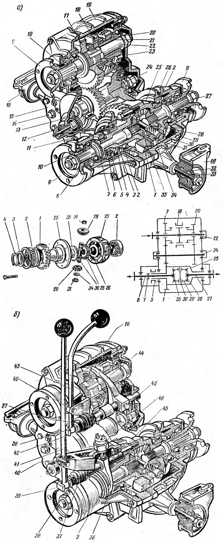
Fig. 32. Transfer case:
a - complete box; b - box drive;
1 - driven gear; 2 - differential bearings; 3, 34 - spring washers; 4, 31 - retaining rings; 5 - differential lock clutch; 6 - differential housing toothed ring; 7 - toothed ring gear of the front axle drive shaft; 8 - front axle drive shaft; 9 - flange; 10 - oil seal; 11 - drain plug; 12 - driven gear of the speedometer drive; 13 - speedometer drive pinion; 14 - filler plug; 15 - front cover; 16 - transfer case suspension bracket; 17 - top gear; 18 - gear shift clutch; 19 - crankcase; 20 - low gear; 21 - bushing; 22 - drive shaft; 23 - back cover; 24 - intermediate shaft; 25 - differential housing; 26 - thrust washer; 27 - rear axle drive shaft; 28 - rear axle drive gear; 29 - satellite; 30 - satellite axis; 32 - rubber cushion; 33 - transfer case suspension axle; 35 - front axle drive gear; 36 - differential lock clutch fork; 37 - case; 38 - lever spring; 39 - differential lock fork slider; 40 - lever axis; 41 - differential lock lever; 42 - gear shift saw slider; 43 - gear shift lever; 44 - gear shift fork; 45 - ball retainer; 46 - differential lock indicator light switch.
In the housing 19 of the transfer case (Fig. 32), cast from an aluminum alloy, the driving 22 and intermediate 24 shafts, the drive shafts of the front 8 and rear 27 axles and the differential housing 25 are mounted on bearings. On the driving shaft 22, helical gears of the highest 17 and lowest 20 gears are freely mounted, having toothed rims and being in constant engagement with the gears of the intermediate shaft 24, which is made in the form of a block of gears. Between the gears 17 and 20 on the shaft, the hub of the gear shift clutch 18 is fixedly fixed, having external splines on which a sliding clutch is mounted. When the highest gear is engaged, the gear shift clutch 18 locks the freely rotating gear 17 on the drive shaft 22, and when the lowest gear is engaged, it locks the gear 20. The block of gears of the intermediate shaft 24 is in constant engagement with the helical driven gear 1, bolted to the differential housing 25, which consists of two parts. On the differential housing, on splines, there is a movable differential lock clutch 5. Inside the differential housing, an axle 30 is installed with two satellites 29, which are in constant engagement with gears 35 and 28, which are connected to the splined ends of shafts 8 and 27 of the drive of the front and rear driving axles of the car. Shaft 8 of the front axle drive, in contrast to shaft 27 of the rear axle drive, is longer and has a toothed ring 7 for locking the differential. When the differential is locked, the movable clutch 5 connects the shaft 8 to the differential housing 25.
The gear shift mechanism of the transfer case includes: shift lever 43, slider 42, fork 44 and ball lock 45. Lever 43 is pivotally mounted on axis 40 in bracket lugs. The lever has a shaped end that enters the groove of slider 42 and is sealed in it by spring 38. Fork 44 is fixed on the slider, entering the groove of gear shift clutch 18. Ball lock 45 holds slider 42 in neutral and engaged positions.
The differential lock drive has a device similar to the gear shift mechanism. The drive consists of a lever 41, a slider 39 with a fork 36 and a ball lock 45.
The transfer case is attached to the car body on two supports installed on axles 33. Each support consists of a bracket 16, into which a rubber cushion 32 is pressed. Adjusting linings are installed under the transfer case suspension supports for its centering and correct installation in relation to the gearbox.