
The engine cooling system is liquid, closed, with forced circulation of liquid. Forced coolant circulation (Tosol-A) in the system is provided by a pump, and the connection of the cooling system with the atmosphere is carried out through special valves (at a certain pressure and vacuum), located in the plugs of the radiator and expansion tank.
The engine cooling system includes a cooling jacket for the head and cylinder block, a radiator, a pump, a thermostat, a fan, an expansion tank, connecting pipes and drain cocks. In addition, the cooling system includes a car body heater and a heater for the intake manifold and carburetor throttle bodies.
Schematic diagram of a car engine cooling system «Niva» VAZ-2121 is shown in fig. 9.
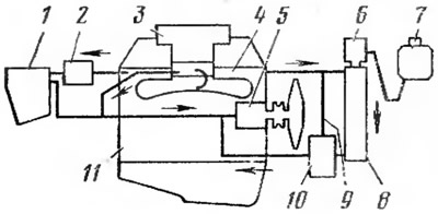
Pic. 9. Schematic diagram of the engine cooling system:
1 - heater; 2 - heater edge; 3 - Carburetor; 4 - cylinder head; 5 - pump; 6 - radiator cap; 7 - expansion tank; 8 - radiator; 9 - bypass pipeline: 10 - thermostat; 11 - cylinder block.
When the engine is cold, the main thermostat valve 10 is closed, and the coolant does not pass through the radiator 8. In this case, the liquid is pumped by the pump 5 into the cooling jacket of the block 11 and cylinder head 4. From the cylinder head, through the bypass pipeline 9, the liquid enters the additional thermostat valve and enters the pump again. Due to the circulation of this part of the liquid, the engine warms up quickly. At the same time, less fluid flows from the cylinder head to the heater (shirt) inlet pipeline and throttle body of the carburetor 3, and with the tap 2 open, into the heater 1 of the car body.
When the engine is warm, the auxiliary thermostat valve is closed and the main valve is open. In this case, most of the liquid from the cylinder head enters the radiator, cools in it and enters the pump through the open main thermostat valve. A smaller part of the fluid, as with a cold engine, circulates through the carburetor heater and the car body heater.
In a certain temperature range, the main and additional thermostat valves are open simultaneously, and the coolant circulates in this case in two circles. The amount of circulating fluid in each circle depends on the degree of opening of the thermostat valves, which ensures automatic maintenance of the optimum temperature regime of the engine.
Expansion tank 7, filled with coolant, communicates with the atmosphere through a rubber valve installed in the tank cap. The tank is connected by a hose to the radiator filler neck, which has a plug with valves. The reservoir compensates for changes in coolant volume, and a constant volume of circulating fluid is maintained in the system.
coolant pump (pic. 10) centrifugal type, provides forced circulation of liquid in the engine cooling system. The pump shaft 5 is installed in the cover 6 in a double-row non-separable bearing 4. The impeller 8 and the fan hub 3 are pressed onto the pump shaft. When the pump shaft rotates, the coolant enters the center of the impeller, is captured by its blades, is thrown to the pump housing under the action of centrifugal force and is directed to the cooling jacket of the engine block. The sealing device 7, installed on the pump shaft, prevents liquid from entering the shaft bearing. The pump and fan are driven by a V-belt from a pulley mounted on the front end of the crankshaft. This belt also rotates the alternator pulley.
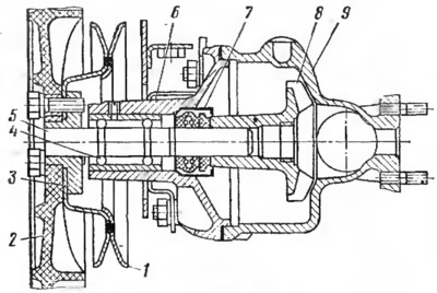
Pic. 10. Coolant pump:
1 - pump pulley; 2 - fan; 3 - hub; 4 - bearing; 5 - shaft; 6 - cover; 7 - sealant; 8 - impeller; 9 - body.
Thermostat (pic. eleven) contributes to the acceleration of engine warm-up and regulates, within certain limits, the amount of coolant passing through the radiator. The thermostat is an automatic valve. It is solid-filled, non-separable, has two inlets 1 and 13, an outlet 6, two valves (main 9, additional 2) and sensing element. The thermostat is installed in front of the coolant pump inlet and is connected to it through pipe 6. Through pipe 1, the thermostat is connected to the engine cylinder head, and through pipe 13 to the lower radiator tank. The sensitive element of the thermostat includes a cylinder 4, a rubber diaphragm 5 and a rod 12. Inside the cylinder, between its walls and the rubber diaphragm, there is a solid filler (fine crystalline wax), which has a high coefficient of volumetric expansion. The main valve 9 of the thermostat starts to open when the coolant temperature is more than 80°C. At temperatures below 80°C, the main valve closes the outlet of the liquid from the radiator and it flows from the engine to the pump, passing through the open auxiliary valve 2 of the thermostat. When the temperature of the coolant rises above 80°C, the solid filler melts in the sensing element and its volume increases. As a result, the rod leaves the cylinder, and the cylinder moves up. At the same time, the additional valve begins to close and at a temperature of more than 94°C blocks the passage of the coolant from the engine to the pump. The main valve in this case opens completely, and the coolant circulates through the radiator.
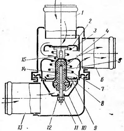
Pic. 11. Thermostat:
1 - inlet pipe from the engine; 2 - additional valve; 3 - additional valve spring; 4 - balloon; 5 - rubber diaphragm; 6 - outlet pipe; 7 - main valve spring; 8 - main valve seat; 9 - main valve; 10 - holder; 11 - adjusting nut; 12 - stock; 13 - inlet pipe from the radiator 14 - filler; 15 - clip.
Radiator (pic. 12) provides heat dissipation of the coolant to the atmosphere. It is tubular-lamellar, has a vertical arrangement of tubes and a horizontal arrangement of cooling plates. The radiator tanks and pipes are brass, and the cooling plates are tinned steel. In the upper tank 3 of the radiator there is a neck 4 through which the cooling system is filled with liquid. The neck is hermetically sealed with plug 5, which has two valves (intake 7 and exhaust 8). The exhaust valve opens at an overpressure in the system of 0.5 kgf/cm2 (0.05 MPa), and the boiled coolant is ejected through the pipe 6 and the connecting hose into the expansion tank. The inlet valve does not have a spring and ensures that the cooling system is connected to the atmosphere through the expansion tank and the rubber valve in its plug, which operates at a pressure close to atmospheric. The inlet valve releases fluid from the expansion tank when its volume in the system decreases (on cooling) and passes into the expansion tank with an increase in volume (when liquid is heated).
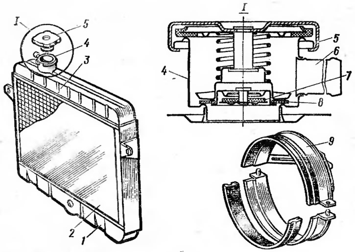
Pic. 12. Radiator:
1 - lower tank; 2 - core; 3 - upper tank; 4 - filler neck; 5 - radiator cap; 6 - vapor outlet pipe; 7 - inlet valve; 8 - exhaust valve; 9 - fan casing.
To direct the air flow through the radiator and more efficient operation of the fan, a fan casing 9, consisting of two halves, is installed behind the radiator.
Fan (see fig. 10) increases the speed and amount of air passing through the radiator. The fan is six-bladed, made of plastic. The blades have rounded ends and are located at an angle to the plane of rotation of the fan. The fan is attached to hub 4 on the coolant pump shaft. Pulley 1 of the coolant pump drive is installed between the fan and the hub.