




The car is equipped with a mechanical, four-speed gearbox with constant mesh gears, synchronizers and manual control.
The gearbox has four forward gears (gear ratios: I - 3.242; II — 1,989; III — 1,289; IV - 1,000) and one gear for reverse movement (reverse gear ratio 3.34). The gears of all gears, except for reverse, are helical, which reduces noise during gearbox operation, and have constant engagement. The gears of the reverse gear are straight-toothed. The gears for forward movement are engaged using synchronizers, and for reverse movement - by moving the intermediate reverse gear. Gear shifting is performed using a lever located on the gearbox housing.
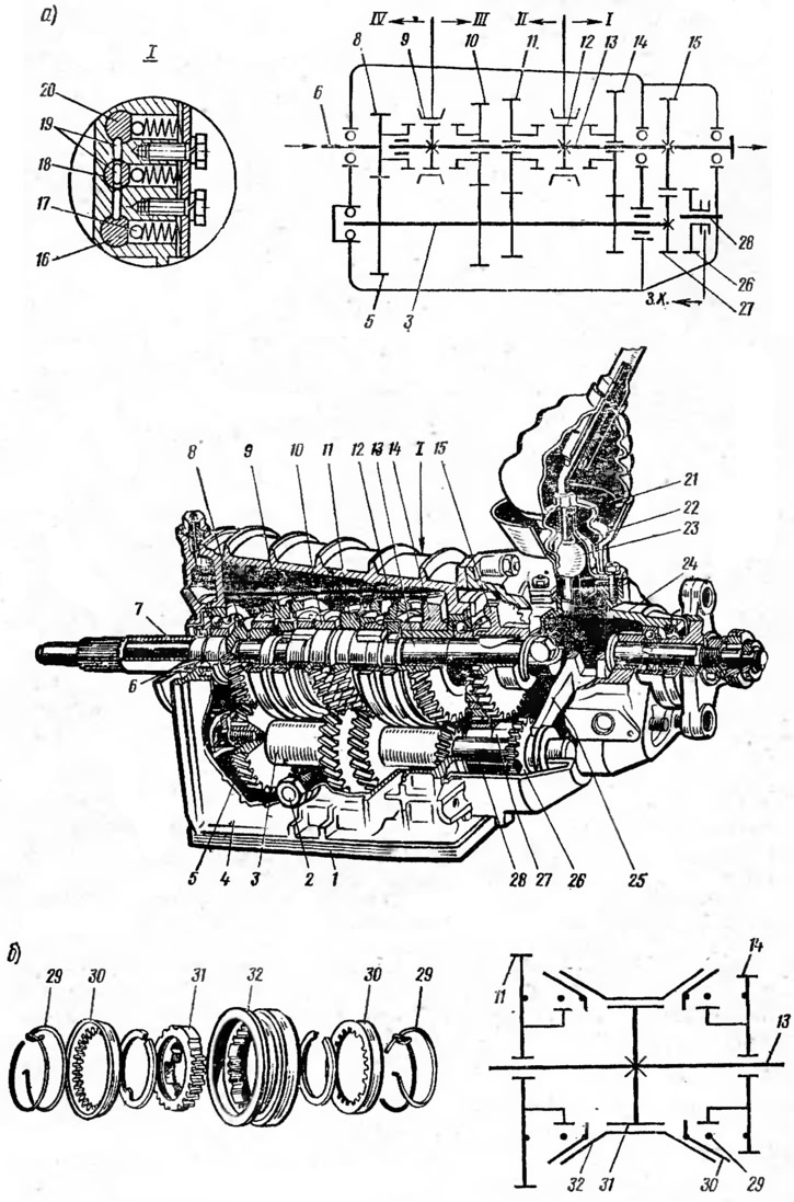
Fig. 28. Gearbox:
a - complete box; b - synchronizer:
1 - bottom cover; 2 - plug for checking the oil level; 3 - intermediate shaft; 4 - crankcase; 5 - intermediate shaft constant mesh gear; 6 - primary shaft; 7 - front cover; 8 - constant mesh gear of the primary shaft; 9 - synchronizer of III and IV gears; 10 - gear 3rd gear; 11 - 2nd gear pinion; 12 - synchronizer of 1st and 2nd gears; 13 - secondary shaft; 14 - 1st gear pinion; 15 - reverse gear; 16 - reverse gear fork slider; 17 - ball retainer; 18 - slider fork for engagement of III and IV gears; 19 - blocking lock; 20 - slider fork for engaging 1st and 2nd gears; 21 - spring; 22 - Ball joint cover; 23 - gear shift lever; 24 - back cover; 25 - Reverse gear fork; 26 - reverse intermediate gear; 27 - intermediate shaft reverse gear; 28 - reverse intermediate gear axle; 29 - spring; 30 - blocking ring; 31 - hub; 32 - coupling.
In the gearbox housing 4 (Fig. 28), the primary (leading) 6, secondary (driven) 13 and intermediate 3 shafts are mounted on bearings. The primary shaft is made as a single piece with gear 8, which is in constant engagement with gear 5 of the intermediate shaft 3, which is a gear block. Gears 10, 11 and 14 of III, II and I gears, respectively, are freely mounted on the secondary shaft, which are in constant engagement with the corresponding gears of the intermediate shaft. The hubs of synchronizers 9 and 12 and reverse gear 15 are also rigidly fixed on the secondary shaft. Intermediate reverse gear 26 is freely mounted on axis 28. When I and II gears are engaged, synchronizer 12 connects gears 11 and 14, respectively, with the secondary shaft of the gearbox. When III and IV gears are engaged, synchronizer 9 connects gear 10 and primary shaft 6 with the secondary shaft, respectively. Reverse gear is engaged by engaging gear 26 with gears 27 and 15.
Synchronizer is designed for silent and shock-free gear shifting. The synchronizer facilitates the driver's work and increases the service life of the gearbox gears. It includes: hub 31, sliding clutch 32, blocking rings 30 and springs 29. The synchronizer hub is fixed on the secondary shaft of the gearbox. It has external splines on which the sliding clutch 32 with internal conical surfaces is mounted. Blocking rings 30 have external conical surfaces and internal teeth with bevels. The blocking rings are constantly pressed by springs 29 to the sliding clutch 32.
The information is published on the website: www.VazBook.ru
The synchronizer operates by using friction forces. The gear can only be engaged after preliminary equalization of the angular velocities of the secondary shaft and the gear pinion. After equalization of the angular velocities due to friction between the conical surfaces of the sliding clutch 32 and the blocking ring 30, the clutch teeth engage with the synchronizer ring gear made on the pinion. In this case, the freely rotating gear on the secondary shaft is connected to the secondary shaft by means of the synchronizer, and the gear is engaged.
The gearbox shift mechanism includes: shift lever 23, sliders 16, 18 and 20 with forks, ball locks 17 and lock 19. Lever 18 is pressed by spring 21 to the spherical surface of ball joint cover 22 and has a shaped end which enters the fork holes when shifting gears. The forks mounted on the sliders enter the recesses of the sliding clutches of synchronizers 9 and 12 and the intermediate gear 26 of reverse. Ball locks 17 hold the sliders in the neutral and engaged positions, and lock 19 prevents simultaneous engagement of two gears. The lock consists of two locking crackers and a pin between them. When moving the middle slider 18, both crackers come out of its recesses and lock the outer sliders 16 and 20, preventing their displacement. When one of the outer sliders moves, the cracker comes out of its recess, blocks the middle slider, and, acting through the pin on the other cracker, also locks the other outer slider.