




Contents: Ball joints ↓ Suspension springs ↓ Stabilizer, suspension arms,…↓ Suspension crossbar ↓ Rubber-metal hinges ↓
Ball joints
Make sure the ball joint mudguards are intact; breaks, cracks, separation of rubber from metal reinforcement, traces of lubricant leakage are unacceptable.
Check for wear on the working surfaces of the ball joints by turning the ball pin manually. Free movement of the pin or its jamming are unacceptable.
A more precise check of the ball joint condition by the size of the radial and axial clearance is carried out on the device 02.8701.9502. To do this, install the ball joint 1 (fig. 4-8, A) into the socket of the device and tighten it with a screw. Install indicator 2 in the bracket of the device so that the indicator leg rests against the side surface of the hinge housing and the indicator arrow is at zero.
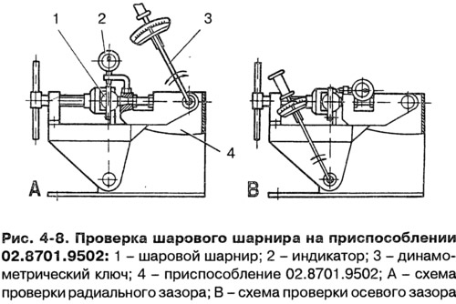
Install torque wrench 3 in the upper socket of the device and, applying a torque of 196 N·m (20 kgf·m) in both directions, determine the total radial clearance in the ball joint using indicator 2. If it exceeds 0.7 mm, replace the joint with a new one.
Similarly, check the axial clearance in the ball joint, having first changed its fastening in the device, as shown in Fig. 4-8, B. The axial clearance in the joint is allowed to be no more than 0.7 mm.
Suspension springs
Carefully inspect the springs. If any deformations are found that may cause malfunction, replace the springs with new ones.
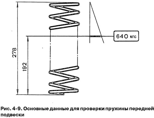
To check the spring's settlement, press it three times until the coils touch. Compress the spring along the spring axis; the support surfaces must match the surfaces of the support cups on the vehicle suspension. Then apply a load of 6276 N (640 kgf) to the spring. According to the length of the spring (Fig. 4-9) under the specified load, they are divided into two classes: class "A" - length greater than 192 mm and class "B" - length equal to or less than 192 mm. Class "A" springs may be unmarked or have white paint markings on the outer side of the coils, class "B" springs are marked with black paint.
Install springs of the same class on the front suspension as those installed on the rear suspension. In exceptional cases, when class "B" springs are installed on the rear suspension, and there are no springs of this class for the front suspension, then class "A" springs are allowed to be installed on the front suspension. However, class "B" springs cannot be installed on the front suspension if class "A" springs are installed on the rear suspension.
Check the technical condition of the insulating gaskets and replace them if they are damaged.
Stabilizer, suspension arms, steering knuckle
Check if the bar is deformed and if its ends are in the same plane; if the deformation is minor, straighten the barbell; if there is significant deformation, replace the rod.
Carefully inspect and make sure that the suspension arms, crossmember and steering knuckles are not deformed or cracked. If cracks or deformations are present, replace the specified parts.
Suspension crossbar
Check the geometric parameters of the cross member with rolling pin 67.8732.9501. If the cross member is significantly deformed, when it is impossible to adjust the front wheel alignment angles with washers, and all other suspension elements are in satisfactory condition, replace the cross member.
Rubber-metal hinges
Signs of the need to replace rubber-metal joints are described in the chapter "Determining the condition of front suspension parts".