




Contents: Removal ↓ Installation ↓
Removal
Raise the rear of the car and place it on stands. Remove the rear wheels.
Disconnect the propeller shaft from the main gear pinion flange.
Disconnect the brake hydraulic hose from the steel tube installed on the bridge and take measures to prevent fluid leakage from the brake system.
Disconnect the rear parking brake cable brackets from the body, remove the front cable release spring, and unscrew the lock nut and adjustment nut to release the rear cable branch. Disconnect the rod 13 from the bracket on the bridge beam (fig. 4-14) the rear brake pressure regulator drive. Disconnect the upper ends of the shock absorbers 25.
(Original source is on the resource: «vazbook.ru»)
Place a hydraulic jack under the rear axle beam. Disconnect the longitudinal 3 and 17 and transverse 24 rods from the brackets on the body, lower the jack and remove the axle.
Proceed to disassemble the suspension:
- remove the shock absorbers from the brackets on the bridge beam;
- disconnect the longitudinal and transverse rods from the brackets on the bridge beam.
The rear suspension parts are shown in Fig. 4-15.
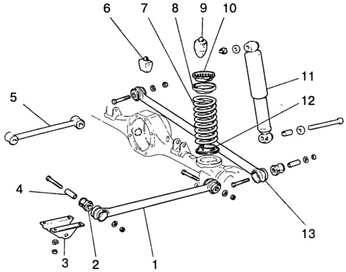
Fig. 4-15. Rear suspension parts:
1 - lower longitudinal bar; 2 - rubber bushing; 3 - bracket; 4 - spacer sleeve; 5 - upper longitudinal bar; 6 - additional compression stroke buffer; 7 - spring; 8 - upper spring cup; 9 - compression stroke buffer; 10 - Upper spring insulating gasket; 11 - shock absorber; 12 - lower spring insulating gasket; 13 - crossbar.
Installation
The rear suspension is installed in the reverse order of removal. In this case, install springs of the same class on the suspension as on the front suspension. In exceptional cases, if the front suspension has class "A" springs, and there are no such springs for the rear suspension, it is permissible to install class "B" springs. If class "B" springs are installed in the front suspension, then only class "B" springs are installed in the rear suspension.
To prevent damage and over-tightening of the elastic bushings of the rods and shock absorbers:
- load the rear of the vehicle so that the distance "X" from the axle beam to the body side member, measured 100 mm from the cross member bracket (Fig. 4-16), is 152 mm; use a torque wrench to tighten the nuts on the bolts securing the longitudinal and transverse rods, as well as on the pins securing the shock absorbers to the axle beam and to the body.
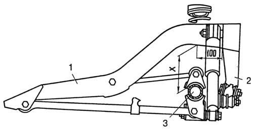
Fig. 4-16. Rear suspension installation diagram:
1 - body side member; 2 - crossbar bracket; 3 - rear axle beam; X=152 mm.