
Disassembly
If the repair of the suspension requires a complete disassembly of its components, then it is more convenient to start directly on the car, after removing the crankcase protective plate and mudguard.
For what do the following:
- unscrew the nut of the pin of the upper ball joint 41 (rice. 4-1) and release the hoses from the brackets;
- having unbent petals of a protective casing, turn out bolts of fastening of a guide of a support and take away it in an assembly with a support aside;
Warning: To prevent damage to the hoses, do not allow the caliper to hang from the hoses.
- mandrel 67.7823.9514 remove the hub cap and unscrew the wheel bearing nut;
- remove the front wheel hub assembly with the brake disc using the ejector 67.7823.9516;
- remove the protective casing of the front brake;
- remove the front suspension shock absorber;
- compress the suspension spring until the lower arm is completely unloaded by lowering the lower suspension arm onto the stand;
- disconnect the ball joint housing from the lower and upper suspension arms and remove the steering knuckle;
- smoothly unload the suspension spring and remove it;
- using ejector 67.7823.9515, knock out the axle and disconnect the lower suspension arm from the cross member;
- disconnect the axle of the upper arm from the cross member and remove the axle assembly with the arm;
Note. Before removing the upper and lower arm axles, count the number of washers at each end of the lower arm axle and on the upper arm axle mounting bolts so that when installing the arm axles, put them in their original places.
- remove the rebound buffer bracket and cross member as described above;
- Using a puller 67.7824.9516, press the pins of the ball joints out of the holes of the steering knuckle.
Details of a forward suspension bracket are shown on fig. 4-7.
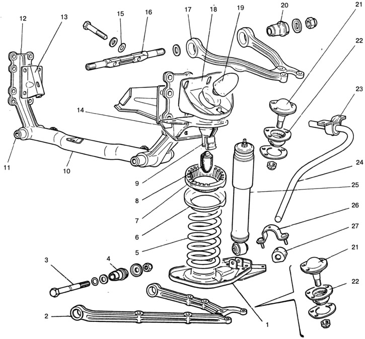
Pic. 4-7. Front suspension details:
1 - lower support cup of the spring; 2 - lower arm; 3 - axis of the lower arm; 4 - rubber-metal hinge of the lower arm; 5 - spring; 6 - upper support cup; 7 - spring insulating gasket; 8 - compression buffer; 9 - compression stroke limiter; 10 - suspension cross member; 11 - cross member bracket bushing; 12 - cross member bracket; 13 - engine mounting bracket; 14 - upper spring support; 15 - adjusting washer; 16 - the axis of the upper arm; 17 - upper lever; 18 - rebound buffer bracket; 19 - rebound buffer; 20 - rubber-metal hinge of the upper arm; 21 - ball joint; 22 - protective cover of the ball joint; 23 - bracket for attaching the rod to the body; 24 - stabilizer bar; 25 - shock absorber; 26 - pillow holder; 27 - pillow.
Assembly
The assembly of suspension units is carried out in the reverse order of disassembly. When assembling the wheel hub, put a layer of Litol-24 grease in the bearing separators and apply it in an even layer into the cavity of the steering knuckle between the bearings in the amount of 40 g for each knuckle.
When installing cross member braces, tighten the inner nut until the gap between the washer and the bracket is selected 3 (rice. 4-6), and the outer one - by the moment specified in Appendix 1.
To prevent incorrect distribution of forces in rubber-metal joints, tighten the nuts of the lever axles under the static load of the vehicle 3140 N (320 kgf). Then check and adjust the angles of installation and convergence of the wheels.