
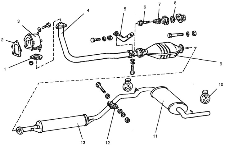
Pic. 9-33. Exhaust gas outlet:
1 - laying of a reception pipe; 2 - gasket; 3 - gas receiver; 4 - receiving pipe; 5 - bracket for fastening the receiving pipe; 6 - bolt; 7 - conical spring; 8 - sealing ring; 9 - neutralizer; 10 - mounting pad; 11 - main muffler; 12 - collar; 13 - additional muffler.
A heat-insulating steel screen is placed above the neutralizer. A sealing gasket 1 is placed between the intake pipe flange and the gas receiver.
The downpipe is connected to the converter flange by means of a movable hinge. A metal-graphite ring 8 with a spherical surface is placed between the flanges, and an inner spherical surface is made in the receiving pipe flange.
The muffler pipes are connected to each other using a clamp 12. The downpipe 4 is fastened with three nuts to the gas inlet and additionally to the bracket 5.
Silencers and pipes are not subject to disassembly and repair and are replaced with new ones.