
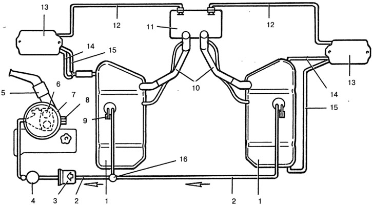
Pic. 9-48. Scheme of the power system with two fuel tanks:
1 - fuel tanks; 2 - fuel supply lines; 3 - fuel fine filter; 4 - fuel pump; 5 - air filter thermostat; 6 - carburetor; 7 - air filter; 8, 9 - plugs; 10 - filler necks of fuel tanks; 11 - hatch for fillers; 12 - ventilation tubes; 13 - separators; 14 - upper steam pipes; 15 - lower steam pipes; 16 - tap-switch.
Crane-switch of fuel tanks (pic. 9-49) located next to the parking brake lever. When running out of fuel from the main tank, switch 2 must be in the position «OSI». To connect an additional fuel tank, after running out of fuel from the main tank, the switch is moved to the position «DOP».
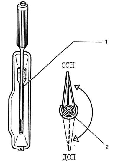
Pic. 9-49. Faucet switch:
1 - parking brake lever; 2 - tap-switch.
On the radio panel on the right there is a switch for the fuel level indicator in the tanks. When you press the upper arm of the key, if the ignition is on, the fuel gauge shows the fuel level in the main tank, and when you press the lower arm - in the additional tank.
The exhaust system differs from the basic one in the use of an extension insert between the exhaust pipe and the additional silencer.