
Removal and installation
Place the shift lever in neutral position and apply the parking brake to the vehicle.
Since fuel pressure remains in the fuel system after the engine is stopped, the first thing to do is to remove the pressure. To do this, disconnect the block of wires of the harness of the injection system from the block of wires of the electric fuel pump. Start the engine and let it run until it stops. Engage the starter for 3 seconds to relieve pressure in the fuel lines. Reconnect the fuel pump wires to the injection system wiring harness.
Disconnect the wire from the outlet «minus» battery.
Remove the air filter and disconnect the throttle cable from the central injection unit.
Disconnect the fuel lines from the central injection unit and plug the ends of the fuel lines to prevent fuel leakage.
Disconnect electrical wires from sensor 4 (pic. 9-3) throttle position, injector 2 and idle speed controller 9.
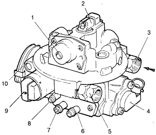
Pic. 9-3. Central injection unit:
1 - fuel pressure regulator; 2 - nozzle; 3 - fitting for fuel supply hose; 4 - throttle position sensor; 5 - fitting for the fuel outlet hose to the tank; 6 - branch pipe for the adsorber purge hose; 7 - branch pipe for the crankcase ventilation hose; 8 - branch pipe for a hose to the absolute pressure sensor; 9 - idle speed regulator; 10 - sector of the throttle valve drive from the pedal in the car.
Remove the vacuum hoses leading to the adsorber and the absolute pressure sensor, as well as the hose of the crankcase ventilation system, from the nozzles of the central injection unit. At the same time, pay attention to the correctness of their connection during subsequent assembly.
Unscrew the mounting studs and remove the central injection unit with the gasket from the inlet pipe. Close the inlet of the inlet pipe with a plug to prevent any objects from entering.
Install the central injection unit in reverse order. At the same time, pay attention to the condition of the seals.
After installation, check the fuel supply pressure as described below.
Note. The sealing gasket installed under the central injection unit and the sealing rings of the fuel lines cannot be reused.
Disassembly and assembly
Unscrew the fastening screws and remove the sensor 10 (pic. 9-4) throttle position, injector 6, fuel pressure regulator, housing 13 of vacuum hose pipes and idle speed regulator 14.
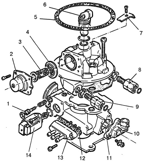
Pic. 9-4. Parts and components of the central injection unit:
1 - factory idle adjustment screw; 2 - fuel pressure regulator cover; 3 - regulator spring; 4 - regulator diaphragm; 5 - air filter gasket; 6 - nozzle; 7 - nozzle holder; 8 - fuel supply fitting; 9 - fuel outlet fitting; 10-throttle position sensor; 11 - throttle valve axis; 12 - laying pipes; 13 - body of vacuum extraction pipes; 14 - idle speed regulator.
Remove the two mounting screws and disconnect the fuel supply housing from the throttle body.
Reassemble in reverse order, paying attention to the condition of the gaskets. When installing the throttle position sensor, pay attention to the coincidence of the flats of the throttle valve axis with the sensor drive.
Check and repair
The nozzle is non-separable. When removing the nozzle, be careful not to damage the electrical connector and spray nozzle.
Note. Do not clean or wash the nozzle with gasoline or other detergents.
Replace nozzle seals with new ones. If there are deposits on the nozzle filters (large diameter - purge filter, small diameter - intake filter) blow them out with compressed air and flush the fuel tank and fuel lines.
When installing the nozzle, apply sealant to the threads of the holder fixing screw.
Fuel pressure control. The spring under the regulator cover is in a compressed state, so be careful when removing the screws securing the cover.
After removing the regulator, check the condition of the valve seat, use a magnifying glass if necessary. The nest should not have chips, dents and surface irregularities. If any of these defects are present, replace the entire fuel supply housing of the central injection unit.
It is recommended to replace the valve diaphragm after each disassembly with a new one. Apply sealant to the screw threads of the regulator cover during assembly.
Note. When installing the fuel pressure regulator, do not distort the diaphragm.
The fuel supply housing of the central injection unit. When assembling the central injection unit, it is recommended to replace the gasket between the fuel supply and throttle bodies with a new one. Align the notches in the gasket with the holes in the throttle body.
Apply sealant to the threads of the housing fixing screws.
Throttle position sensor. When installing the sensor, put the throttle in the closed position and, turning the sensor counterclockwise, align the flats of the roller with the sensor drive. Tighten the fastening screws.
Note. Do not clean or wash the throttle position sensor and idle speed control with gasoline or other detergents.
Idling regulator. Replace gaskets with new ones.
Before installing the regulator to the throttle body, check the distance from the mounting flange to the end point of the regulator valve. If the valve is extended too far, damage to the regulator may result.
The distance must be less than 23 mm. If the new regulator has more than 23 mm, then you can use your hand, shaking the valve from side to side, to press it into the regulator.
With a regulator that has been in operation, it is not allowed to push the valve in manually, so as not to damage the regulator. For this purpose, it is necessary to use a diagnostic tool or a special monitor.
After installing the idle speed controller and the central injection unit, connect a diagnostic tool to the diagnostic block and instruct the controller to reset the idle speed controller parameters.
Throttle body. When assembling the central fuel injection unit, it is recommended to replace the sealing gasket of the fuel supply housing with a new one.
Clean the surfaces of the throttle body and vacuum tube housing of the old gasket material. Replace the gasket with a new one.
Fuel pressure control
The purpose of this control is to check the tightness of the connections of the fuel supply system, check the operation of the pressure regulator and check the operation of the electric fuel pump.
Depressurize the fuel supply system as described above to remove the central injection unit.
Connect the electrical wires to the electric fuel pump. Disconnect the fuel line from the inlet fitting of the central injection unit and connect a pressure gauge through the tee between the fitting and the fuel line.
Put the ignition key in position «Ignition», check the tightness of the pressure gauge connection and its readings. The pressure should be within 190-210 kPa. If there is no pressure, check by ear whether the electric fuel pump turns on when the ignition key is turned to the position «Ignition» (the operation of the pump and the clicks of the operation of its relay can be heard while in the car).
If the electric fuel pump does not turn on, it is necessary to check the electrical circuits of the pump.
After 2 seconds of operation, the electric fuel pump should turn off, since when the engine is not running, the controller does not receive reference signals for the position of the crankshaft. To turn on the pump again, you must turn off the ignition for 10 seconds and turn it on again.
After stopping the electric fuel pump, the pressure may decrease slightly and stabilize, or, conversely, increase if the engine is warm. If the pressure does not stabilize and decreases, turn on the electric fuel pump and immediately after it stops, pinch the fuel supply hose to the central injection unit.
If at the same time the pressure does not drop, then check the tightness of the fuel lines from the tank to the central injection unit, as well as the fuel fine filter, then repeat the pressure test in the fuel supply system.
Low pressure (below 190 kPa) may be caused by a malfunctioning fuel pressure regulator or a limited capacity of the fuel delivery system.
The throughput of the fuel supply system can be determined from the fuel consumption for draining. If necessary, replace the fuel fine filter with a new one.
The operation of the pressure regulator can be checked by reading the pressure gauge, for which disconnect the drain hose and lower it into the prepared container. Turn on the electric fuel pump, pinch the drain hose and check the pressure on the pressure gauge that the pump can create. Release the hose. The gauge will show the set pressure of the regulator valve. Replace pressure regulator if necessary.
Increased pressure in the fuel supply system (over 210 kPa) may be caused by a malfunctioning fuel pressure regulator or increased resistance to fuel draining into the tank. To check, connect a pressure gauge to the fuel supply system, disconnect the drain hose in the engine compartment and lower it into a container. Turn on the electric fuel pump and check the pressure in the system according to the pressure gauge.
If the pressure is too high, replace the fuel pressure regulator. If this does not help, then find and eliminate the cause of increased resistance to fuel drain.
Electric fuel pump
Removal and installation. To remove the pump from the vehicle, disconnect the electrical wires from the pump and relieve pressure in the fuel supply system as described above to remove the central injection unit.
Disconnect the fuel lines from the pump and unscrew the nuts securing it to the fuel tank. Remove the electric fuel pump from the tank.
Install the electric fuel pump in reverse order.
The electric fuel pump is not disassembled and cannot be repaired. In case of failure, replace it with a new one.
Gasoline vapor recovery system
Inspect the hoses and adsorber. If there are cracks or damage to the body, replace the adsorber with a new one.
If leaks occur, check the tightness of the hose connections. If fuel leaks from the adsorber, replace it with a new one.