
Setting the fuel level in the float chamber
The fuel level necessary for the normal operation of the carburetor is ensured by the correct installation of serviceable elements of the locking device.
Correct installation of float 1 (pic. 2-90) check with gauge 4, for which you install it perpendicular to cover 2, which you hold horizontally with the floats up. There must be a gap of no more than 1 mm between the gauge along the contour and the floats.
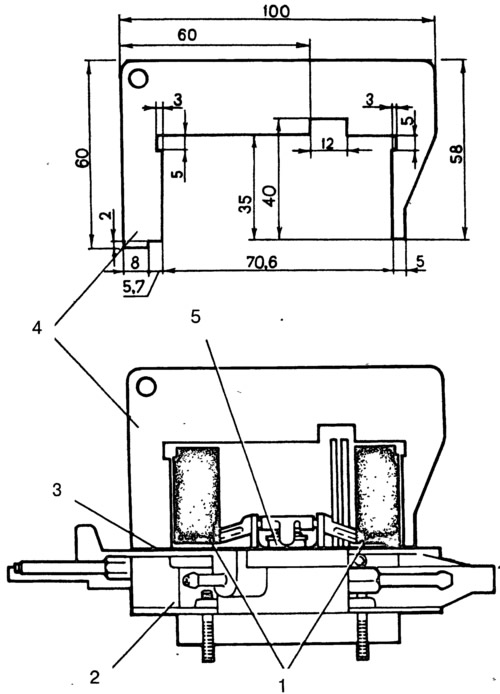
Pic. 2-90. Setting the fuel level in the carburetor float chamber:
1 - float; 2 - carburetor cover; 3 - sealing gasket; 4 - gauge for checking the position of the floats; 5 - needle valve.
Adjust if necessary by bending the tongue and float arms. The bearing surface of the tongue must be perpendicular to the axis of the needle valve 5 and must not have dents or nicks.
Trigger Adjustment
When turning lever 4 (rice. 2-86) control of the air damper 5 fully counterclockwise, the air damper must be fully closed under the action of the spring 7. If the damper is not closed, eliminate the cause of jamming.
With the air damper fully closed, press manually on the rod 3 of the starting device until it stops. In this case, the air damper 5 should open by 3.0 mm (starting clearance B). If necessary, adjust the gap with screw 2.
Throttle valve 12 of the first chamber with a fully closed air damper should be ajar by 1.1 mm (starting gap C). If necessary, adjust this gap with screw 10.
Carburetor Drive Adjustment
With the pedal fully depressed 7 (rice. 2-87) throttle valve control, the throttle valve of the first chamber must be fully open and the rod 15 must not have an additional stroke. With the pedal 7 released, the throttle must be completely closed. If this is not the case, adjust the position of the pedal and throttle with the tip 10 at the front end of the longitudinal link 1.
In the air damper drive, fasten the end of the cable 3 so that when the handle 5 is extended, the air damper is completely closed, and when it is recessed, it is completely open.
Engine idle adjustment
Adjustment is provided by adjusting screw 2 (pic. 2-91) quality (composition) mixture and adjusting screw 1 of the mixture quantity. The adjusting screw 2 is closed with a plug 4. To access the screw, remove the plug with a corkscrew.
Pic. 2-91. Idle adjustment screws:
1 - adjusting screw for the amount of the mixture; 2 - quality adjusting screw (composition) mixtures; 3 - sealing ring; 4 - plug of the adjusting screw.
Idle speed adjustment must be carried out on a warm engine (coolant temperature 85-90°С), with adjusted gaps in the gas distribution mechanism, with the correct ignition timing and with the choke valve fully open.
Using the adjusting screw 1 of the amount of the mixture, set the engine crankshaft speed within 750-800 min using the tachometer of the stand-1.
Adjusting screw 2 quality (composition) mix to achieve carbon monoxide content (SO) in exhaust gases no more than 1.5% at a given position of the screw 1 (CO content is reduced to 20°C and 101.3 kPa (760 mmHg Art.).
Screw 1 restore the crankshaft speed to 750-800 min-1.
If necessary, use the adjusting screw 2 to restore the CO content to no more than 1.5%.
At the end of the adjustment, sharply press the throttle pedal and release it, the engine should increase the crankshaft speed without interruption, and when it decreases, it should not stall. In case of engine stop, use screw 1 to increase the crankshaft speed within 750-800 min-1.
Install a new plastic plug 4 into the hole for adjusting screw 2 of the mixture quality.
Checking the operation of the second camera blocking mechanism
Turn the choke control lever counterclockwise until the choke is fully closed. Then turn the axis lever 19 (rice. 2-89) throttle control until the damper 23 of the first chamber is fully opened, while the throttle damper 24 of the second chamber must remain in the closed position.
Turn the choke control lever clockwise until it stops, and the throttle control lever 19 until the dampers are fully open. If the second chamber throttle does not open, repair the problem. The reason may be jamming of the lever 20 of the lock of the second chamber or disconnection of the spring 21 of the lock lever.