
A car has no unit, mechanism or assembly more important than brakes, and this imposes a special responsibility for their inspection and maintenance. On VAZ cars - combined brakes. The fronts are discs and the rears are drums.
When you press the pedal 6 (pic. 28) brake pusher master cylinder moves the piston. The compressed brake fluid moves through the tubes to the wheel cylinders of the front 3 and rear 10 brakes. The pistons of the wheel cylinders, experiencing fluid pressure, press the pads against the discs or drums. If a hydraulic vacuum booster 5 is included in the hydraulic drive circuit (for VAZ-2103 cars, VAZ-2105, VAZ-2106, VAZ-2107, VAZ-2121), then as the force of pressing the brake pedal increases, it enters into work, which facilitates the work of the driver. It is very important that the front and rear brakes have separate drives. This means that a rear brake failure does not leave the car with no brakes at all.
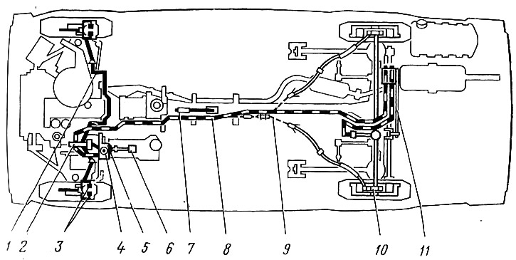
Pic. 28. Scheme of the brake system:
1 -- front brake drive circuit; 2 - main cylinder; 3 - wheel cylinders of the front brakes; 4 — a reservoir of a hydraulic drive of brakes; 5 - hydraulic vacuum booster; 6 - brake pedal; 7 — parking brake lever; 8 rear brake drive circuit; 9 - parking brake cable; 10 wheel rear brake cylinder; 11 - pressure regulator.
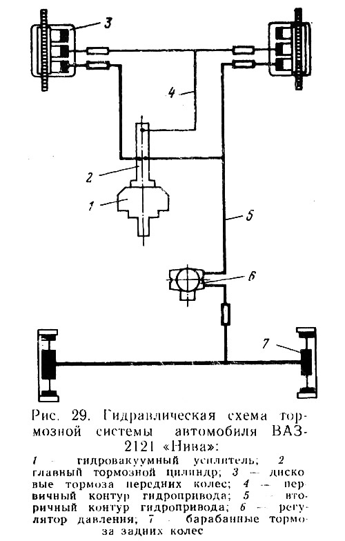
The brakes of other models of VAZ cars differ noticeably from the brakes of a VAZ-2121 car «Niva». An all-wheel drive car, of course, has a shortened wheelbase and a higher center of gravity. These design features have a significant impact on the distribution of loads on each axle at the time of braking. At the car VAZ-2121 «Niva» in particularly difficult conditions, the front axle and separate drives for the front and rear brakes turned out to be not as effective as on all other models.
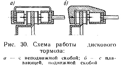
I had to «Niva» apply a special hydraulic drive scheme (pic. 29), at which the front disc brakes are always operational. The design of the front brake itself has also undergone some changes. If traditional disc brakes are made with a fixed caliper (pic. 30, a), then on «Niva» for the first time in the domestic automotive industry, the design of front disc brakes with a movable caliper was used (pic. 30. b), which provided a dense layout of the hubs and wheel brakes.
However, all the positive things that have been said about the brakes become effective only with constant attention and care for them. No maintenance should be complete without checking the condition of the brakes.
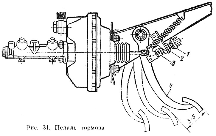
Pedal free play 4 (pic. 31) brakes when the engine is not running for cars VAZ-21013, -2103, 2105, -2100, -2107 and -2121 «Niva» should be 3-5 mm. These millimeters can be obtained by adjusting the brake light switch 1. To do this, loosen the nut 2, set the brake light switch so that its buffer 3 slightly touches the pedal stop. Achieve the desired free play and tighten the nut.
Now let's talk about the front wheel brakes. They are disc (pic. 32), because when braking, most of the load falls on the front axle, and disc brakes have a significantly greater braking effect. To find out if the vacuum booster is working, press the brake pedal 5-6 times with the engine off. Then they press the pedal and at half its stroke they stop and start the engine. With a working vacuum booster, the pedal should go forward. If this does not happen, you need to look for where air is sucked in.
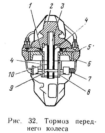
The lining thickness of the new brake pads is 11mm and they can work as long as they are 1.5mm thick. After that, they are replaced with new ones. To find out what the condition of the pads 4 is, the wheels must be turned to the left and right sides and, accordingly, inspect the pads of the right and left brakes. If the pad linings are worn, get ready to perform the operation to replace the pads.
Tools and accessories for this operation: a screwdriver, pliers, a hammer, firmware, a mounting blade, a combination wrench for removing wheels, a metal brush, a jack, wheel stops, a douche, a container for brake fluid. Since the wheels will have to be removed, care must be taken that the car is on a level area with the parking brake engaged. With chocks under the wheels, jack up one of the front wheels. Using the combination wrench, unscrew the wheel mounting bolts and remove the wheel. The pads are replaced with new ones in the following sequence:
- with a metal brush and wiping ends, remove dirt from the caliper 2;
- pliers take out the cotter pins that fix the fingers 9;
- using a firmware or an old finger and a hammer that have worked out their time, they knock out a finger. Fingers almost always offer stubborn resistance. Usually on such fingers for 15-20 minutes they put a rag, abundantly moistened with kerosene. The fingers are removed together with the springs 7;
- remove flat springs 8 pads 10;
- the pads are removed from the disc 3 with a mounting spatula. Before performing this operation, it is necessary to take a little brake fluid from the reservoir with a syringe. This should be done, since the divorced pads will move the pistons 6 deep into the cylinders 5, and the liquid displaced by the pistons will rush into the tank and may spill out;
- pliers remove the pads 10 from the caliper carefully (finger touch) check the condition of the rubber cuffs 1.
New pads are installed in reverse order. Those who have taken into account the recommendations and lubricated the fingers of the pads before starting the operation of the car will not experience difficulties when dismantling them. It is advisable to lubricate the pins and sockets with each installation of the pins.
It is only necessary to carefully monitor that the lubricant does not get on the surfaces of the pads and disc.
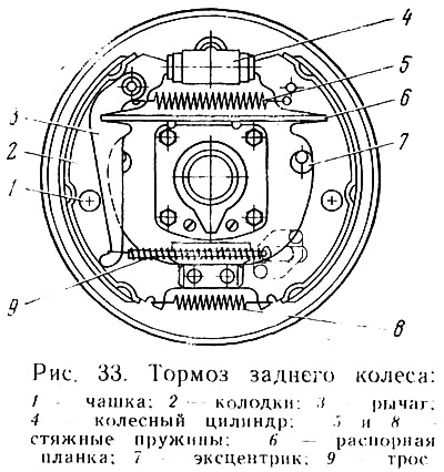
Rear wheel brakes - drum type, with one wheel cylinder and two pads (pic. 33). Replacing the pads with new ones is a simple operation, if not for one thing «But». Removing the drums can be very difficult, even in a service station environment. Numerous tips and suggestions were put forward on how to remove the drums, but, unfortunately, there were no really effective ones among them.
Of all the devices offered recently, the puller turned out to be the most effective (pic. 34), made by a Cherepovets motorist from a piece of an old spring. The bent edge of the lever 3 is hooked to the edge of the drum 1. A steel bar 2 is inserted into the hole on the fixture and, resting against the end of the axle shaft, the drum is shifted from its place.
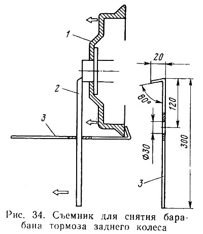
The operation is greatly simplified if, before starting operation, the contact surfaces of the edges of the drum hole and the axle shaft flange are lubricated. In this case, it is enough to use two bolts that are screwed into the technological holes until the drum moves from its place.
After removing the drum, replacing the pads is not difficult (see fig. 33):
- first disconnect the end of the cable 9 from the lever 3 and remove the lever;
- disconnect the coupling springs 5 and 8;
- the cups 1 of the swivel struts are rotated and removed together with the struts, springs and lower cups;
- remove the pads 2, removing them from the grooves of the pistons of the wheel cylinder 4;
- remove the spacer bar 6.
Install new pads in the reverse order, taking into account that when installing the pad, you must first put the axle of the pad drive lever in place, and mount the spacer bar after installing the support posts. After replacing the pads, it is imperative to adjust the position of the pads using eccentrics 7.
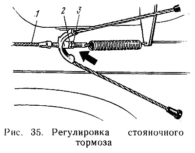
Parking brake (pic. 35) It is an integral part of the vehicle's braking system. Its role is great. How many exciting stories can be heard where the parking brake played the role of a savior. Residents of mountainous areas can appreciate its special role. But for the parking brake to really work properly, it must be properly adjusted. The state of adjustment is most conveniently checked on a natural slope. Install on such a slope (at 30°) car, tighten the brake lever three to five clicks and see what happens next. If the car will not move down, then everything is in order. Otherwise, the stroke of the lever must be adjusted and the operation must be performed with a 13 mm wrench and pliers on the inspection ditch or on the overpass in this order:
- move the parking brake control lever to the lowest position;
- pull the lever up two clicks and down (from the ditch) use a 13 mm wrench and pliers to release locknut 3;
- by turning nut 2, tighten cable 1, and then lock nut 2 with a lock nut.
If air gets into the hydraulic brake drive system, this is already an emergency. First of all, you need to find the cause and eliminate it. Air can enter the system if individual parts and assemblies have been replaced. Once in the system, air begins to distort the force transmitted by the liquid. In any case, the air must be removed from the system. The operation is simple, but requires at least two participants and it is advisable to perform it on a flyover or a viewing ditch. To perform the operation, you will need: an 8 mm spanner wrench, which was proposed to be made or purchased for unscrewing the screws of the contact plates of the breaker-distributor, the rubber hose included in the tool kit, a vessel for brake fluid and 0.25-0.30 kg of the fluid itself «Neva», cleaning material.
Before starting the operation, it is necessary to fill the tanks of the main cylinders with brake fluid to a normal level, that is, to the lower edge of the filler hole, and clean the caps of the fittings intended for pumping the system from dirt. Be careful with caps. It can be said about them that «small spool but precious». Only thanks to them, the fitting holes are not clogged with dirt. Caps are often lost, and, having discovered that, it is necessary to clean the holes and put a cap of our own production on the fitting (from a piece of rubber hose with a wire tied end).
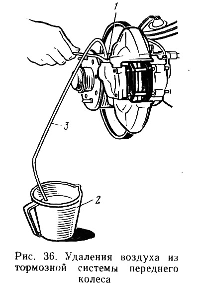
Removal of air from the system is performed by two people in the following sequence (pic. 36):
- a key of 8 mm in size is thrown onto the hexagon of fitting 1;
- one end of hose 3 is put on the fitting head, the other is lowered into vessel 2 with brake fluid;
- one person standing in the inspection ditch unscrews the fitting one and a half to two turns, and the other person sitting in the car at this time sharply presses the brake pedal, then gently releases and sharply presses it again. This action must be performed until air bubbles stop appearing;
- as soon as the release of bubbles stops, you should press the pedal and keep it in this position until the person below tightens the fitting to failure.
The operation must be repeated on each wheel and each time before starting to pump, top up the brake fluid to the norm. The liquid drained from the system can be reused, but it must first be settled and filtered.
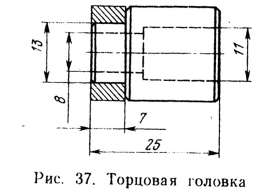
If the fittings have not been touched for a long time, it may happen that an elegant ring wrench only remembers the edges of a rusted fitting and nothing more. The way out is to use an 8 mm socket from a set of sockets. Just like that, you will not put the head on the fitting. It must be prepared, i.e., machined on one side as shown in fig. 37.
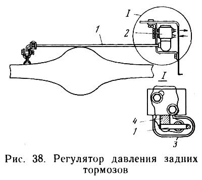
A few words about pressure regulator 2 (pic. 38) rear brakes. It serves to regulate the braking force of the rear wheels depending on the load on the rear axle and road conditions. The sharper the braking, the more the proportion of the total mass attributable to the front wheels increases. Since the rear axle turns out to be unloaded, the force of the brakes of the rear wheels may turn out to be greater than the force of adhesion of the wheels to the road surface, and this, in turn, can cause the wheels to slip, which means low braking efficiency, loss of control, skidding. The presence of a pressure regulator eliminates this disadvantage by automatically changing the pressure of the brake fluid in the hydraulic drive of the rear wheels. Violation of the location of the pressure regulator distorts its operation and practically nullifies its capabilities.
The lack of necessary information about the pressure regulator leads to the fact that they do not pay attention to it at all. Whether it works or just takes up space - few people are interested.
Practice shows that neglect of the pressure regulator 2 takes place not only on the part of car owners, but also on the part of specialists at most service stations. To control the correct location of the pressure regulator on the body, a special device is required, simple, but not commercially available. There is such a device at the service station, but for some reason it is ignored, but in vain.
Over time, the piston 4 of the regulator becomes motionless, rusted, so it is important to be able to independently check the performance of the pressure regulator.
Install the car on the inspection ditch, clean the regulator and protective cover 3 from dirt and carefully remove the protective cover; wipe dry the torsion-piston connection; while your assistant will forcefully press the brake pedal, you watch the protruding part of the piston. If the pressure regulator is working properly, the piston should move (0.5—0.9 mm) and begin to tighten the torsion lever 1. To be sure, check again and again that the piston is moving.
Having found that the pressure regulator is fully functional and there is no leakage of brake fluid, lubricate the protruding part of the piston with DT-1 or Litol-24 grease (Put 5-6 g of this grease into the protective cover and put it back in place). If the piston is rusted, the pressure regulator must be replaced.