

Valve knock
If the car is regularly serviced, then this defect should not occur, since the gaps are maintained in the normal range all the time. The main source of valve knock is increased clearances between the levers and camshaft cams. High-quality clearance adjustment depends only on the performer. Small things such as worn or deformed threads of the adjusting bolt, careless tightening of the locknut are likely to become sources of gap violation.
There are sometimes more serious reasons leading to valve knocking:
- increased wear of camshaft lobes and rockers (leverage);
- broken valve spring
- wear of the bearing surfaces of the camshaft bearing housing.
If we turn to the guarantees of the plant, then the resource of the camshafts is 70 thousand km. Cases when the shaft serves 100-150 thousand km are not rare.
The camshaft, a pair of cam-lever work almost under extreme conditions, since all engines installed on VAZ vehicles are high-speed. It is clear that any violation of the regime, no matter how it is expressed, dramatically affects the durability of the camshaft.
One of the main factors leading to the rapid wear of the parts of the gas distribution mechanism is the poor quality of the oil. If you poured low-quality oil into the engine, you can be sure that it will not withstand the loads that occur in the friction zone. The oil film will collapse, and the rubbing pairs will find themselves in the most difficult conditions. Under such conditions, the temperature at the point of contact of two metal surfaces will almost instantly reach 900-950°C and, as a result, scuffing of the ground surfaces of the cam, and then its very intensive wear.
Similar phenomena occur if you forgot to replace the oil and air filters on time.
Why does the factory recommend changing the oil filter after 10 thousand km? Yes, because its drainage valve is designed for only 10 thousand km. It no longer retains oil. To fill such a filter with oil, the pump must work for at least 10 seconds, and during this time the engine parts will experience oil starvation. Approximately the same thing happens when the oil is dirty or when there is a suction of uncleaned air, etc.
The use of low quality oil has revealed additional reasons that contribute to the deterioration of the working conditions of rubbing surfaces.
Even if you follow all the recommendations of the factory, this does not mean that the camshaft of your car engine will definitely last a long time. It may happen that after 30-35 thousand kilometers it will be necessary to change the camshaft and levers. Puzzled by this outcome, the most inquisitive motorists began to investigate this problem and determined that those shafts whose hardness of the heat-treated layer is lower than the required one are subject to intensive wear, that those cams whose oil channel holes are located somewhat further from the tops of the cams than the rest are subject to progressive wear..
In the course of research, a number of proposals have appeared that allow creating a more favorable operating mode for the cams. This includes the installation of oil baffles in the camshaft housing, and the transfer of oil channels, and an increase in the power of oil pumps, etc.
The simplest method proposed by a motorist is that the required cam lubrication mode is provided without increasing the oil supply to the camshaft channels. Just more oil is directed to the top of the cam.
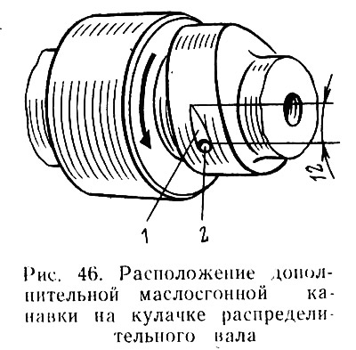
This is ensured as follows: from the edge of hole 2 (pic. 46) in the direction of the cam, with the help of an abrasive stone, groove 1 is selected in the form of a drop. Oil flows through an artificially made channel (fading away) and much more intensively than before, it is captured by the lever and directed to the top of the cam.
To establish the true state of the cams and levers, just run your finger over their surface. Wear is clearly felt. The confirmation of the defect is the difficulties that you experience when it is necessary to adjust the gaps between the cams and levers. A camshaft with worn cams must either be repaired or replaced with a new one along with the levers.
It is desirable to replace the camshaft, springs or camshaft bearing housing in the conditions of a service station, since there are certain subtleties during assembly and, in addition, after installing new parts, it will be necessary to perform a familiar set of operations: change the oil and oil filter; adjust the chain tension; set the ignition timing; adjust the gaps between the levers and camshaft cams.
For those who still decide to replace the camshaft with levers or other parts of the gas distribution mechanism on their own, we remind you of the following: the surfaces of the camshaft bearing journals and the surfaces of the cams must be well polished and must not be damaged (traces of jamming, scratches, steps, etc.). If, as a result of the inspection, you came to the conclusion that the camshaft can still serve, still check its radial runout. To do this, you need a camshaft bearing journals (extreme) install on two prisms and measure the radial runout of the middle necks with an indicator. It should not exceed 0.02 mm. The gap between the camshaft journals and the bearings in the housing must not exceed 0.2 mm. The internal bearings of the housing surface must be the same as the bearing journals of the shaft, i.e. not have any damage, including marks. The camshaft pulley bolt must be installed on the sealant.
If the wear on the camshaft cam does not exceed 1 mm, then you can leave it in place for some more time. To determine the condition of the camshaft cams and levers, you must:
- remove the cover of the gas distribution mechanism;
- turn the crankshaft using the crank or a special key to turn the engine crankshaft (cars VAZ-2105 and -2107) until the marks on the gear and the camshaft housing are aligned;
- loosen the chain or belt tension;
- unlock the lock washer under the bolt securing the gear;
- make sure that the gear does not turn when the bolt securing it is unscrewed. Unscrew the bolt with a sharp movement;
- lightly tapping on the inside of the gear, remove it together with the chain. It is advisable to temporarily fasten the gear and chain together in order to maintain their relative position. Lower the bundle of these parts down, allowing the gear to take place between the damper and the tensioner shoe;
- loosen the nuts of the camshaft thrust flange, unscrew the nuts securing the bearing housing and carefully lift it together with the shaft;
- without fail, check the location of the centering bushings of the housing, which are often lost when dismantling the housing;
- check the levers. Their working surfaces should be mirrored. At levers, only those of them that have wear can be restored (scratches, scratches, gouges) does not exceed 0.3 mm. If the wear is greater, such a lever is hopeless.
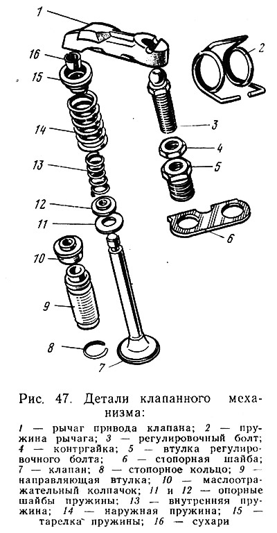
Remove lever 1 (pic. 47) presents no difficulty. Pressing on its end resting on the valve stem 7, turn it around the adjusting bolt 3 and remove. It should be remembered:
- where each of the removed levers was located in order to return each of the levers to its place;
- that the surfaces of the levers in contact with the sphere of the adjusting bolt must be mirrored. Any deviation (risks, chips) - a sign of rejection;
- that the recesses at the ends of the valve stems should not exceed 0.5 mm. Such wear can be repaired using a diamond file and polishing paste.
To deal directly with the camshaft, it must first be removed from the housing. The back side of the cams will tell you about the quality of the gap adjustment over the past period. If the surface does not have scratches, scratches and a dark color, then the necessary gaps were provided. The back side, polished to a shine, is evidence of constant contact, i.e., a small gap. If traces of friction are visible only from the edge, then the lever installed with a warp is to blame. This happens when the lever spring is deformed. Remember that for a free-lying spring, the ends must be in the same plane, and the distance between them must be 35 mm.
The most critical operation is the removal of irregularities in the contact surfaces of the cams and levers. The technique and tool can be very diverse depending on your capabilities and abilities. Car enthusiasts use everything from grinders to needle files, bars and abrasive skins. It is important to grind and polish all irregularities, while removing the minimum possible surface hardened layer. Another condition for the effectiveness of the work done is the thorough cleaning of the repaired camshaft and levers from abrasive particles. To do this, it is enough to wash the parts in kerosene, gasoline and blow them with compressed air.
Installing the camshaft in place is a delicate and responsible operation. The assembly order is as follows:
- Gently insert the camshaft, richly lubricated with engine oil, into the housing so that it is easy to install the thrust flange into the annular groove of the front neck;
- fix the thrust flange with two nuts;
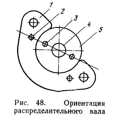
- install camshaft 5 (pic. 48) so that the centering pin 3 and the hole 4 for the bolt in the end of the shaft are on the same axis with the technological hole 2 in the thrust flange 1;
- loosen the locknut of the adjusting bolts and tighten the latter by 3-5 mm to avoid deformation of the valve stems when the crankshaft is turned;
- clean, liberally lubricated with engine oil, put the levers together with the springs in their places, using the marks made during dismantling. Remember: the ends of the valves must be securely located in the grooves of the levers, and the springs must be installed without distortion;
- install the bearing housing on the cylinder head studs and, strictly following the recommendations of the factory, tighten the nuts evenly, using a torque wrench without fail. The tightening torque must not exceed 22 Nm.
When installing the camshaft gear, no force should be applied. Put the gear on the shaft, making sure that the locking pin on the end of the camshaft enters its hole. Another hole on the gear is designed for the mustache of the washer located under the gear mounting bolt. When finally tightening the bolt, ensure that the gear does not turn.
When self-replacing the camshaft on car engines VAZ-2105 and VAZ-2107 it must be remembered that the gland holder at the front end of the shaft should be placed on the sealing mastic in order to prevent oil from penetrating into the area of the drive timing belt and oiling it. In the absence of the mastic used by the factory, a paint that does not dissolve in oil can be used.
One more warning. Be careful when tightening the timing cover nuts. The shelf of this part is very fragile and cannot bear the application of force to it.
After installing the camshaft with the housing and levers in place, it is necessary to perform such operations as tensioning the timing chain or belt and adjusting the gaps between the cams and levers.
Knock of the crankshaft
An extraneous knock that appeared unexpectedly in the engine causes concern for every motorist - experienced or novice. First of all, you need to figure out which engine mechanism makes a knock. The easiest way to determine this is with a stethoscope. At the Chernihiv auto parts plant (GAZ branch) a special technical stethoscope has been developed, which makes it possible to determine by ear the condition of the engine and its units by the noise generated. To do this, it is enough to attach an acoustic probe to a particular node. Some motorists successfully diagnose the engine with their own stethoscopes. An old oiler is soldered to a steel bar. To accurately determine the source of noise, the end of the steel bar is alternately applied to various parts of the running engine, and the oil can is applied to the ear. Due to the fact that the thin bottom of the oil can is an excellent membrane, even the smallest sound cannot be hidden from hearing.
The knock of the crankshaft is metallic, deaf. Its frequency increases with an increase in the frequency of rotation of the crankshaft. If the axial clearance of the crankshaft is much larger than normal, the knock acquires a sharp tone with uneven intervals, especially noticeable during smooth acceleration and deceleration of the speed.
The main causes of crankshaft knocks:
- too early ignition. If that's the reason, then it's not a big deal. It is necessary to adjust the ignition timing setting, and the knock should disappear;
- the use of oil that does not correspond to those recommended by the plant in terms of grade and quality. If the defect is not started, that is, it is detected immediately, as soon as the knock appears, the situation can be corrected by draining the oil, flushing the system with detergent oil and filling the engine with fresh oil, as provided for in the instructions;
- insufficient oil pressure. This causes malfunctions of the oil pump, pressure reducing valve, clogging of the channels of the lubrication system. Given that in order to correct defects, it is necessary to disassemble the engine (let partially), you should not take on such work at home.
There are a number of other reasons that can cause crankshaft knocking: increased clearance between the journals and main bearing shells, misalignment and ovality of the main journals, increased clearance between the thrust half rings and the crankshaft, loosening of the flywheel bolts to the crankshaft. In all cases, disassembly of the engine is necessary, therefore, the listed repairs should be carried out at a service station.
Knocking rod bearings
Usually the knock of the connecting rod bearings is sharper than the knock of the main bearings. It is heard at idle and in the neutral position of the gear lever. The knock increases with increasing crankshaft speed. To determine which of the four connecting rods turned out to be defective, it is necessary to exclude one of the cylinders from work in turn, removing the high voltage wire from the candle. The reasons that give rise to the knock of connecting rod bearings are very similar to the previous ones: wrong ignition timing; low quality oil; large gaps between necks (now crank) crankshaft and liners; ovality or taper of the connecting rod journals; misalignment of the axes of the upper and lower heads of the connecting rod. And again you have to contact the service station, as the engine will have to be disassembled.
Knock of piston pins
The sound of the piston pins is metallic and sharp. Many drivers often confuse this knock with a detonation knock, but they have a different nature. The knock of piston fingers, unlike detonation, is better heard at idle speed. As a result of intensive development of the pin or connecting rod head, the gaps increase, which generates a knock.
To eliminate the defect, they change the fingers or connecting rods, but in both cases, special equipment, a heating furnace and great skill are needed.