
Pay attention to the position of your left foot while driving. For most novice motorists, the foot seems to be tied to the clutch pedal. The worst thing for clutch is if a car with a novice driver has stalled. Under these conditions, if none of the more experienced intervenes in time, the clutch can last a very short time.
Clutch failures can be divided into two categories: fixable without removal and disassembly; eliminated only by replacing failed parts with new ones.
The first category includes malfunctions associated with a violation of the free play of the clutch pedal and air ingress into the hydraulic clutch drive system. Pedal free play is a serious factor affecting the proper operation and life of the clutch. The operation of the clutch without slip depends on the free play. Incomplete clutch disengagement is often accompanied by noise when shifting gears and is caused by an increase in clutch pedal free play.
If air has entered the hydraulic system, first of all it is necessary to find out which part or connection is causing the air to enter the system. It is necessary to carefully inspect the entire route from the fluid reservoir to the clutch slave cylinder. Air leakage is possible through cracks in the tubes if the sealing rings of the main or working cylinders are damaged. Where there are fluid leaks, air leakage is also possible. Tubes with cracks, of course, are replaced with new ones, and the system is pumped. If liquid leaks are found in the main or working cylinders, they are removed, disassembled and the o-rings are changed - the most likely sources of leaks.
If one of the components or parts of the hydraulic clutch drive is to be replaced, it is necessary first of all to drain the brake fluid (remember that the clutch hydraulic system is filled with brake fluid «Neva»). It is very easy to do this. One end of the hose should be put on fitting 8 (see fig. 27) working cylinder, and lower the other end into a clean vessel; having unscrewed the fitting by 1/2-3/4 turn, press the clutch pedal until all the fluid has flowed out of the hydraulic drive. Suppose, during the test, fluid leakage from the master cylinder is detected. This is already a malfunction related to the second category. The cylinder must be removed, disassembled and the failed parts replaced. To remove the master cylinder, you need to unscrew only two nuts securing it to the pedal bracket and remove the flexible hose connecting the reservoir to the cylinder.
The master cylinder should be disassembled on a clean table, with a bath of brake fluid, a brush for washing parts and lint-free napkins at hand. Particular care must be taken to ensure that the details of the main (working) cylinders had no contact with mineral oils, gasoline, kerosene, diesel fuel. Remember that rubber parts that work in the environment of brake fluid «Neva», do not tolerate these materials.
Starting disassembly, remove the rubber protective cap 12 (see fig. 26) and a retaining ring, then piston 5, sealing rings 4 and 13, floating piston 3 and spring 15. Having disassembled the main cylinder, evaluate the state of the cylinder mirror. It should not have scratches or scratches. By replacing the o-rings with new ones and flushing all the parts in brake fluid, the master cylinder can be assembled and installed in place. Lubricate parts before assembly with brake fluid only.
If the main suspicions fell on the rubber parts of the working cylinder, the cylinder must be removed, for which disconnect the spring 6 (see fig. 27), unscrew the tube, remove the pusher and unscrew the two screws securing the cylinder. The disassembly of the cylinder begins with the protective cap 11. Then the pusher 3 and the piston 12 are removed. Compressed air will help push the piston out, for which connect the pump hose to the fitting 8, and close the opening of the housing plug with your finger. To disassemble the piston, remove the retaining ring, washer, spring. After replacing the seal or ring 10 and thoroughly flushing the body 9, plug 7 and all disassembled parts in the brake fluid, the working cylinder is assembled and installed in place.
The presence of air in the system is easy to determine by the behavior of the clutch pedal. It will move with little resistance (fall through). Remove air by pumping the system. This is a simple operation. The only inconvenience is that it must be done together and on a viewing ditch or overpass. The operation is very similar to bleeding the brakes and is performed in the following sequence:
- remove the protective cap from the fitting 8 (see fig. 27) to bleed the clutch drive and remove dirt from the fitting;
- add fluid to the hydraulic drive reservoir to the required level (to the lower edge of the filler neck);
- put a hose on the fitting head and lower its lower end into a vessel with liquid;
- unscrew the fitting 1/2-3/4 turn and sharply press the clutch pedal, and then slowly release it. These exercises must be performed until the air stops leaving the system.
In the process of pumping, make sure that the end of the tube is not exposed (Otherwise, air will be sucked into the system), connecting the reservoir to the master cylinder, and the end of the bleed hose was constantly immersed in liquid.
The second category of malfunctions can also be attributed to: warpage of the driven disk; loosening of rivets, uneven surfaces or breakage of the friction linings of the driven disk; breakage of the plates connecting the thrust flange with the clutch cover; jamming of the hub of the driven disk on the splines of the drive shaft; loosening the compression spring rivets.
To find out which of these defects is responsible for the incomplete disengagement of the clutch, it is necessary to remove the clutch and inspect each of its parts. Remove the clutch on a viewing ditch or overpass. Getting to the clutch is not so easy. There is a lot of work, although not very difficult, since the clutch is clamped on one side by the engine, and on the other by the gearbox, cardan shaft, etc. When removing the clutch, the car must stand securely on a viewing ditch or overpass with stops under the front wheels and Racks under the rear sockets for the jack (rear axle needs to be lifted). Since you will have to manually turn the driveshafts while standing below, do not forget to set the gear lever to neutral and disconnect the wires from the battery.
To get to the clutch, you need to remove the gearbox. You will have to start this work in the cabin in the following order:
- remove the front floor mat and the outer cover of the gear lever;
- unscrew the four screws and remove the plastic cover of the hatch of the gear lever and the seal;
- while pressing the lever rod down, use a thin screwdriver to remove the thrust ring from the groove on the lever rod;
- since the exhaust pipe of the silencers and they themselves will interfere with removing the box, it is necessary to loosen the clamp connecting the exhaust pipe to the silencer pipe and remove them together with the silencer hangers. Disconnect also a collar of fastening of a reception rough to a transmission;
- from the engine compartment, unscrew the nuts securing the exhaust pipe to the exhaust manifold, after which the exhaust pipe can be removed;
- unscrew the bolts securing the clutch housing cover to its lower part;
- unscrew the bolt securing the ground wire to the clutch housing;
- remove the cotter pin from the end of the pusher;
- remove the clutch slave cylinder along with the tube connecting it to the master cylinder. Then it will not be necessary to pump the hydraulic drive system;
- unscrew the nuts and remove the propeller shaft safety bracket;
- disconnect the flexible shaft of the speedometer from its drive; disconnect the propeller shaft. To facilitate the removal of the cardan shaft, service stations use a simple device - a hoop with a tension screw. The hoop is put on an elastic sleeve and the sleeve is compressed with a screw. In this position, unscrew the nuts and, turning the cardan shaft, remove the bolts securing the gearbox flange to the flexible coupling. It is advisable to make such a device yourself, as it will come in handy and help with the assembly of the transmission;
- move the disconnected cardan shaft together with the clutch to the side;
- end (best articulated) unscrew the bolts securing the starter to the clutch housing with a wrench;
- unscrew the bolts securing the rear engine mount to the cross member, and then the nuts securing the cross member to the body;
- from the available funds, build a reliable support for the gearbox from below and only after that unscrew the four bolts securing the clutch housing to the cylinder block. It should be added that this operation requires a special socket wrench with a hinge.
The gearbox freed from fasteners must be carefully moved back until the end of the gearbox input shaft is out of the clutch. Under no circumstances should the end of the box drive shaft rest on the thrust flange of the clutch pressure spring.
So, 95% of the work is done. It remains to disconnect the clutch from the engine flywheel. Just in case, mark the relative position of the clutch and flywheel. This will come in handy during assembly if you have to reinstall the old clutch. After unscrewing the mounting bolts, remove the clutch cover together with the pressure plate. Do this carefully, remembering that there is a driven disk between the clutch and the flywheel, which can fall on your feet.
To inspect the clutch (pic. 52), does not require any complex equipment. It is necessary to have a table, the surface of which would imitate the plane of the flywheel, and a ring 4 made of any hard material with a thickness of 8.2 mm.
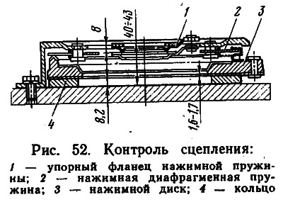
The clutch cover should be fixed on the table and pressed 4-5 times on the pressure spring flange (approximate pressing force 1.37-1.42 kN). With 8 mm of clutch engagement travel, the pressure plate should move 1.6-1.7 mm.
Clutch cover; together with the pressure plate must be changed, provided that the size 40-43 mm, i.e. the distance from the table surface to the working surface of the friction ring of the thrust flange, does not exceed 48 mm or the size 1.6-1.7 mm is not less than 1.4 mm.
Inspection of parts and clutch assemblies should tell you what to do. If you find warping, the driven disk must be replaced. If the plates connecting the thrust flange to the casing are broken, or the spring rivets are loosened (pressure) you will have to replace the clutch cover together with the pressure plate. It happens that the cause of incomplete disengagement of the clutch is the jamming of the driven disk hub on the splines of the gearbox input shaft, i.e., there are burrs on the splines of the driven disk shaft or hub, which prevent the disk from moving freely.
This defect is eliminated as follows: the detected burrs are sanded, and then the slots are wiped and lubricated with a thin layer of grease LSTs-15 or Litol-24.
Having clarified all the questions of interest, the clutch can be installed in place. In addition to the tool provided in the driver's kit, an old, outdated gearbox drive shaft is also needed to ensure the alignment of the driven disk with the crankshaft bearing. When installing the gearbox in place, in most cases the input shaft will not enter due to misalignment of the splines. To overcome this obstacle, it is necessary to turn on the gear and, rotating the flange (from the opposite end of the box), help the drive shaft find its place.
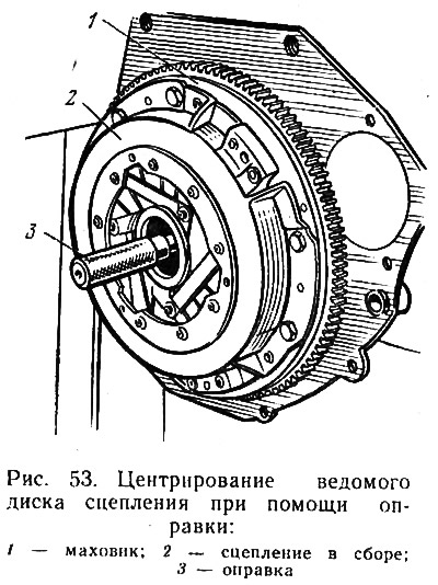
In order not to confuse how to install the driven disk, we remind you: the driven disk with the protruding part of the hub with an annular groove is installed towards the gearbox, the casing assembly with the pressure plate is applied, and only then the casing and the driven disc are centered relative to the bearing (pic. 53), i.e. insert a mandrel or an old roller. The centered casing is bolted to the flywheel, and then everything that was removed is installed.