





Fig. 9-26. Schematic diagram of the carburetor electromagnetic valve control system: 1 - carburetor limit switch; 2 - electromagnetic valve; 3 - control unit; 4 - ignition coil; 5 - fuse box; 6 - ignition switch
Before checking the unit's functionality, make sure that the wires are connected correctly (see fig. 9-26).
The functionality of the control unit is checked using a voltmeter (with measurement ranges of 0-15 V) in the following order:
- disconnect the green wire from the carburetor limit switch and connect the tip of this wire to ground;
- connect the voltmeter to the control unit using a special adapter connector 2 (Fig. 9-27);
- start the engine and, gradually increasing the rotation speed, monitor the voltmeter readings: after starting the engine, the voltmeter should show a voltage of at least 10 V, and at the moment the valve is turned off - a sudden drop in voltage to a value of no more than 0.5 V;
- after turning off the valve, gradually reduce the rotation speed until the valve turns on; the voltmeter should show a sudden increase in voltage of at least 10 V;
- set the crankshaft speed within 2200-2300 min⁻¹, disconnect the tip of the wire going to the limit switch of the crankshaft from the ground, and then reconnect it to the ground; when the wire is disconnected from the ground, the valve should turn on, and when connected to the ground, it should turn off.
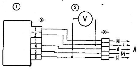
Fig. 9-27. Control unit test diagram: 1 - control unit, 2 - adapter connector with voltmeter; A - to the vehicle's wiring harness
It is permissible to check the functionality of the control unit without a voltmeter and adapter connector by the characteristic click of the valve when turning it off and on.